Service Manual (KLZ1000C) — page 287 of 762
Crankshaft/Transmission › Crankshaft Main Bearing Insert/Journal Wear Inspection
Text on this page
CRANKSHAFT/TRANSMISSION 9-23
Crankshaft and Connecting Rods
Crankshaft Runout Inspection
• Measure the crankshaft runout.
If the measurement exceeds the service limit, replace the
crankshaft.
Crankshaft Runout
Standard: TIR 0.02 mm (0.0008 in.) or less
Service Limit: TIR 0.05 mm (0.0020 in.)
Crankshaft Main Bearing Insert/Journal Wear
Inspection
• Split the crankcase (see Crankcase Splitting(9-9)).
• Place a strip
Cut strips of plastigage (press gauge) to journal width.
• installed in theoncorrect
each journal parallel to the crankshaft
position.
• Tighten the crankcase bolts to the specified torque (see
Crankcase Assembly(9-10)).
NOTE
○Do not turn the crankshaft during clearance measure-
ment.
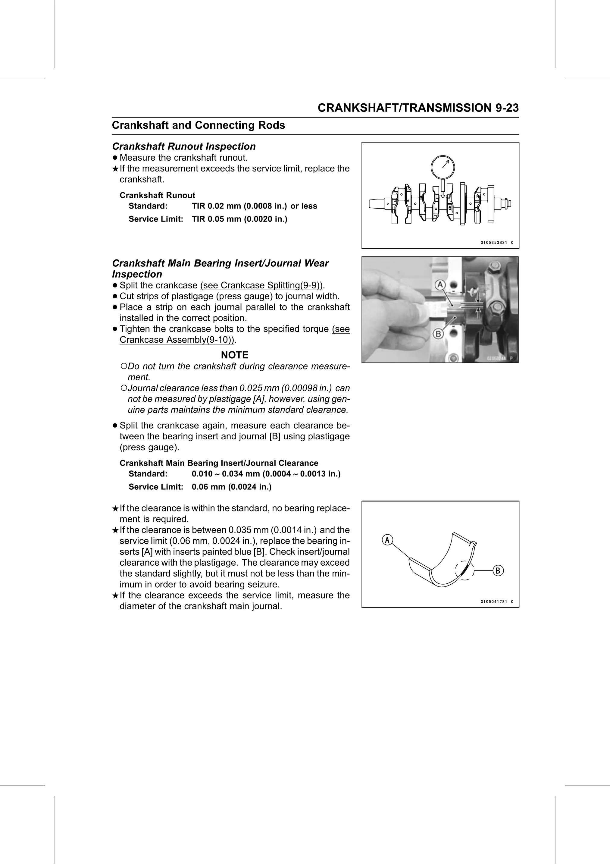
○Journal clearance less than 0.025 mm (0.00098 in.) can
not be measured by plastigage [A], however, using gen-
uine parts maintains the minimum standard clearance.
• Split the crankcase again, measure each clearance be-
tween the bearing insert and journal [B] using plastigage
(press gauge).
Crankshaft Main Bearing Insert/Journal Clearance
Standard: 0.010 0.034 mm (0.0004 0.0013 in.)
Service Limit: 0.06 mm (0.0024 in.)
If the clearance is within the standard, no bearing replace-
ment is required.
If the clearance is between 0.035 mm (0.0014 in.) and the
service limit (0.06 mm, 0.0024 in.), replace the bearing in-
serts [A] with inserts painted blue [B]. Check insert/journal
clearance with the plastigage. The clearance may exceed
the standard slightly, but it must not be less than the min-
imum in order to avoid bearing seizure.
If the clearance exceeds the service limit, measure the
diameter of the crankshaft main journal.