Service Manual (KLZ1000C) — page 562 of 762
Electrical System › Meter Unit Inspection
Text on this page
16-80 ELECTRICAL SYSTEM
Meter, Gauge, Indicator Unit

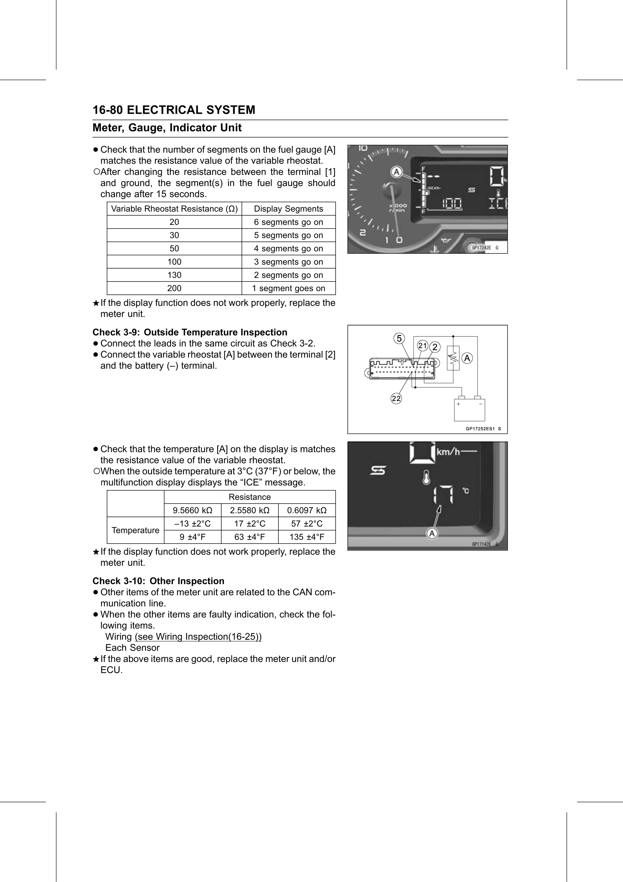
• Check that the number of segments on the fuel gauge [A]
  matches the resistance value of the variable rheostat.
○After changing the resistance between the terminal [1]
    and ground, the segment(s) in the fuel gauge should
    change after 15 seconds.
      Variable Rheostat Resistance (Ω)    Display Segments
                     20                   6 segments go on
                     30                   5 segments go on
                     50                   4 segments go on
                    100                   3 segments go on
                    130                   2 segments go on
                    200                   1 segment goes on
    If the display function does not work properly, replace the
    meter unit.
Check 3-9: Outside Temperature Inspection
•Connect the leads in the same circuit as Check 3-2.
•Connect the variable rheostat [A] between the terminal [2]
 and the battery (–) terminal.

• Check  that the temperature [A] on the display is matches
  the resistance value of the variable rheostat.
○When the outside temperature at 3°C (37°F) or below, the
    multifunction display displays the “ICE” message.
                                    Resistance
                      9.5660 kΩ     2.5580 kΩ     0.6097 kΩ
                      –13 ±2°C       17 ±2°C       57 ±2°C
      Temperature
                          9 ±4°F     63 ±4°F       135 ±4°F
    If the display function does not work properly, replace the
    meter unit.
Check 3-10: Other Inspection
•Other items of the meter unit are related to the CAN com-
 munication line.
•When the other items are faulty indication, check the fol-
 lowing items.
   Wiring (see Wiring Inspection(16-25))
   Each Sensor
 If the above items are good, replace the meter unit and/or
 ECU.