Service Manual (KLZ1000C) — page 632 of 762
Self-Diagnosis System › Intake Air Temperature Sensor Circuit
Text on this page
17-30 SELF-DIAGNOSIS SYSTEM
Intake Air Temperature Sensor (Service Code 13) (DTC P0110, P0112)
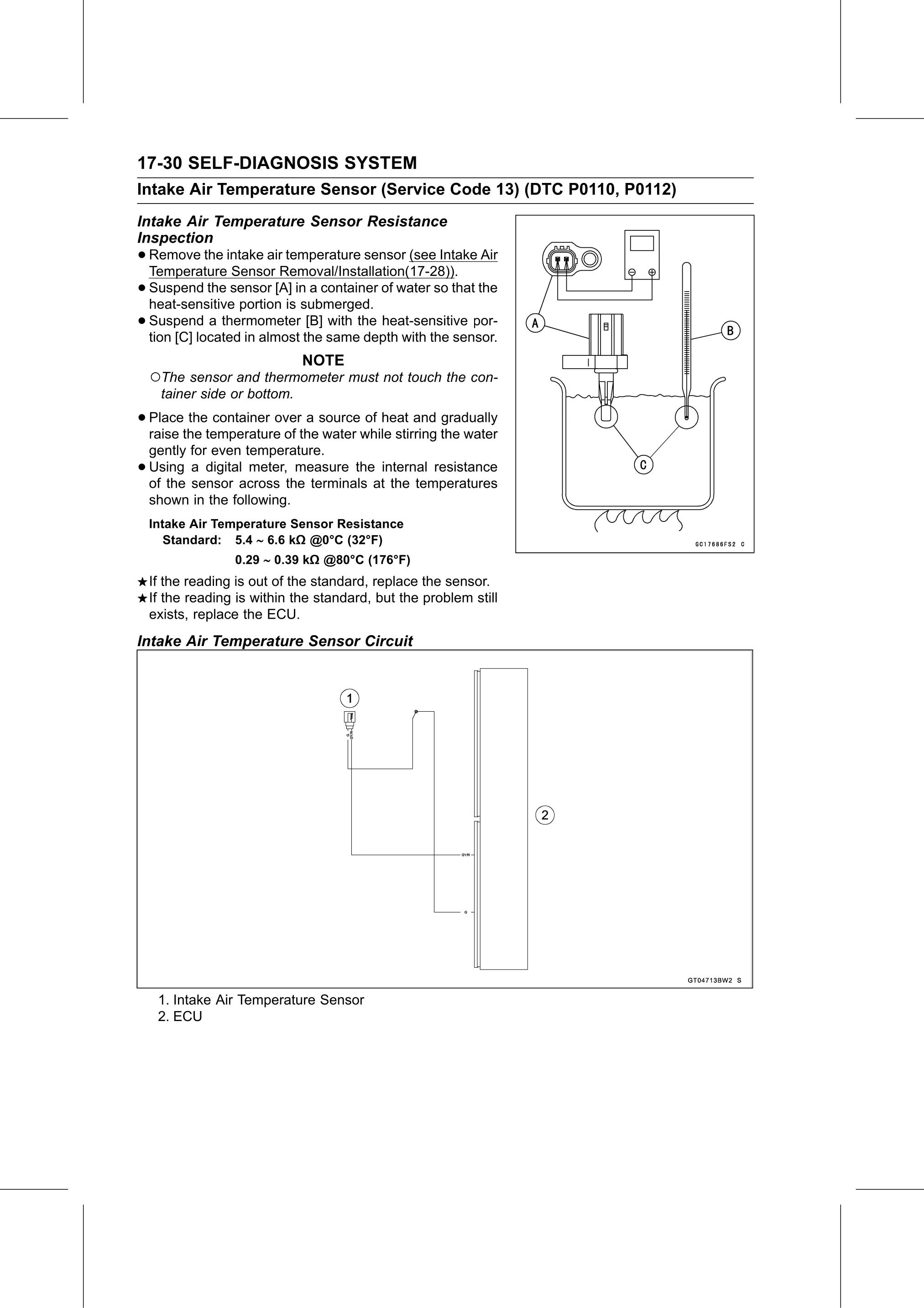
Intake Air Temperature Sensor Resistance
Inspection
• Remove the intake air temperature sensor (see Intake Air
Temperature Sensor Removal/Installation(17-28)).
• Suspend the sensor [A] in a container of water so that the
heat-sensitive portion is submerged.
• Suspend a thermometer [B] with the heat-sensitive por-
tion [C] located in almost the same depth with the sensor.
NOTE
○The sensor and thermometer must not touch the con-
tainer side or bottom.
• Place the container over a source of heat and gradually
raise the temperature of the water while stirring the water
gently for even temperature.
• Using a digital meter, measure the internal resistance
of the sensor across the terminals at the temperatures
shown in the following.
Intake Air Temperature Sensor Resistance
Standard: 5.4 6.6 kΩ @0°C (32°F)
0.29 0.39 kΩ @80°C (176°F)
If the reading is out of the standard, replace the sensor.
If the reading is within the standard, but the problem still
exists, replace the ECU.
Intake Air Temperature Sensor Circuit
1. Intake Air Temperature Sensor
2. ECU