Service Manual (KLZ1000C) — page 692 of 762
Self-Diagnosis System › Rear Wheel Rotation Sensor Signal Abnormal (Service Code B44)
Text on this page
17-90 SELF-DIAGNOSIS SYSTEM
ABS Service Codes
Front Wheel Rotation Sensor Wiring Inspection
(Service Code B43)
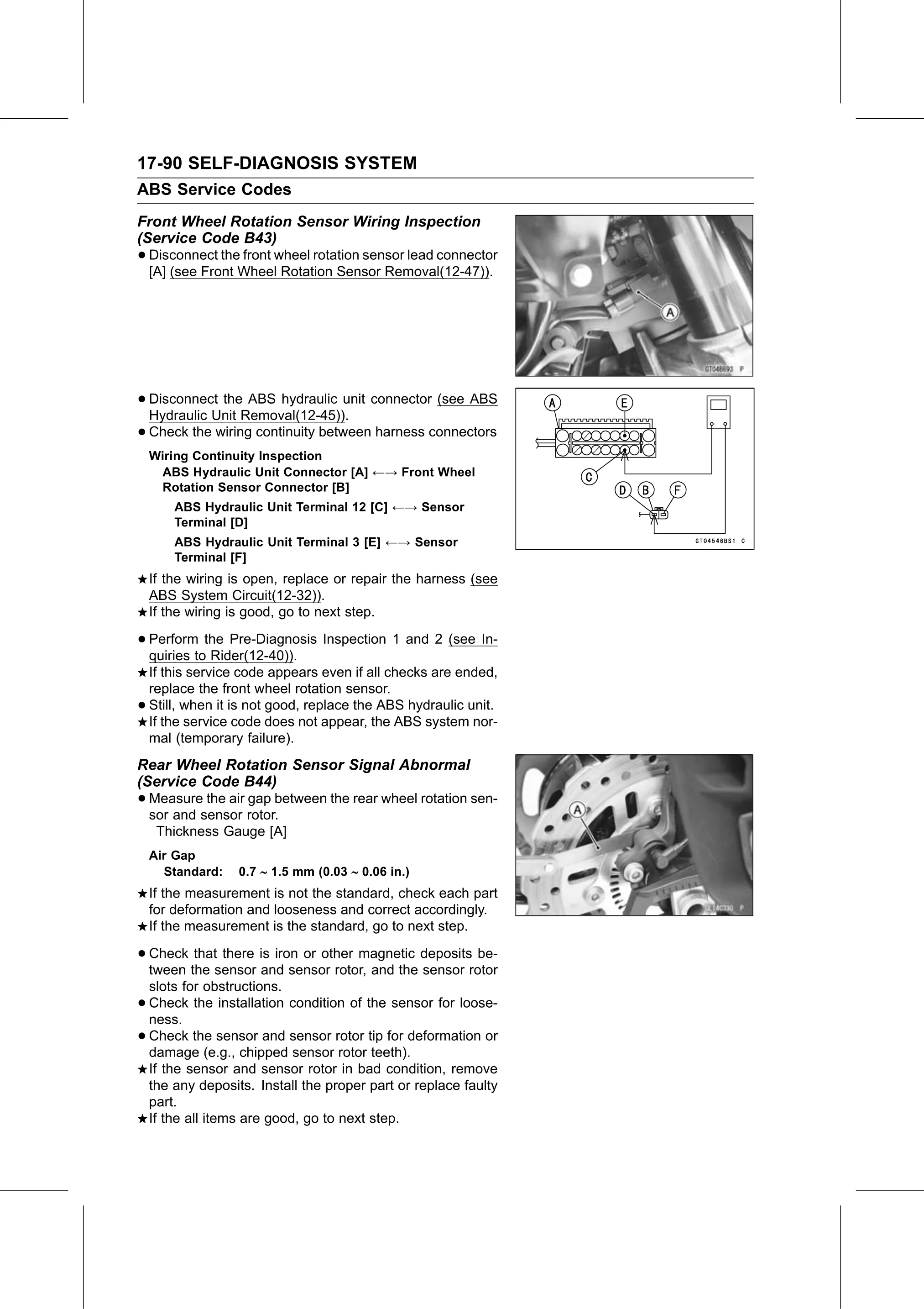
• Disconnect the front wheel rotation sensor lead connector
[A] (see Front Wheel Rotation Sensor Removal(12-47)).
• Disconnect the ABS hydraulic unit connector (see ABS
Hydraulic Unit Removal(12-45)).
• Check the wiring continuity between harness connectors
Wiring Continuity Inspection
ABS Hydraulic Unit Connector [A] ←→ Front Wheel
Rotation Sensor Connector [B]
ABS Hydraulic Unit Terminal 12 [C] ←→ Sensor
Terminal [D]
ABS Hydraulic Unit Terminal 3 [E] ←→ Sensor
Terminal [F]
If the wiring is open, replace or repair the harness (see
ABS System Circuit(12-32)).
If the wiring is good, go to next step.
• Perform the Pre-Diagnosis Inspection 1 and 2 (see In-
quiries to Rider(12-40)).
If this service code appears even if all checks are ended,
replace the front wheel rotation sensor.
• Still, when it is not good, replace the ABS hydraulic unit.
If the service code does not appear, the ABS system nor-
mal (temporary failure).
Rear Wheel Rotation Sensor Signal Abnormal
(Service Code B44)
• Measure the air gap between the rear wheel rotation sen-
sor and sensor rotor.
Thickness Gauge [A]
Air Gap
Standard: 0.7 1.5 mm (0.03 0.06 in.)
If the measurement is not the standard, check each part
for deformation and looseness and correct accordingly.
If the measurement is the standard, go to next step.
• Check that there is iron or other magnetic deposits be-
tween the sensor and sensor rotor, and the sensor rotor
slots for obstructions.
• Check the installation condition of the sensor for loose-
ness.
• Check the sensor and sensor rotor tip for deformation or
damage (e.g., chipped sensor rotor teeth).
If the sensor and sensor rotor in bad condition, remove
the any deposits. Install the proper part or replace faulty
part.
If the all items are good, go to next step.