Service Manual — page 157 of 715
Fuel System (DFI) › Intake Air Pressure Sensor #2 Inspection (Service Code 16/DTC P2227)
Text on this page
FUEL SYSTEM (DFI) 3-67
Intake Air Pressure Sensor #2 (Service Code 16) (DTC P2226, P2227, P2228)
Intake Air Pressure Sensor #2 Inspection (Service
Code 16/DTC P2227)
(Checking sensor for various vacuum)
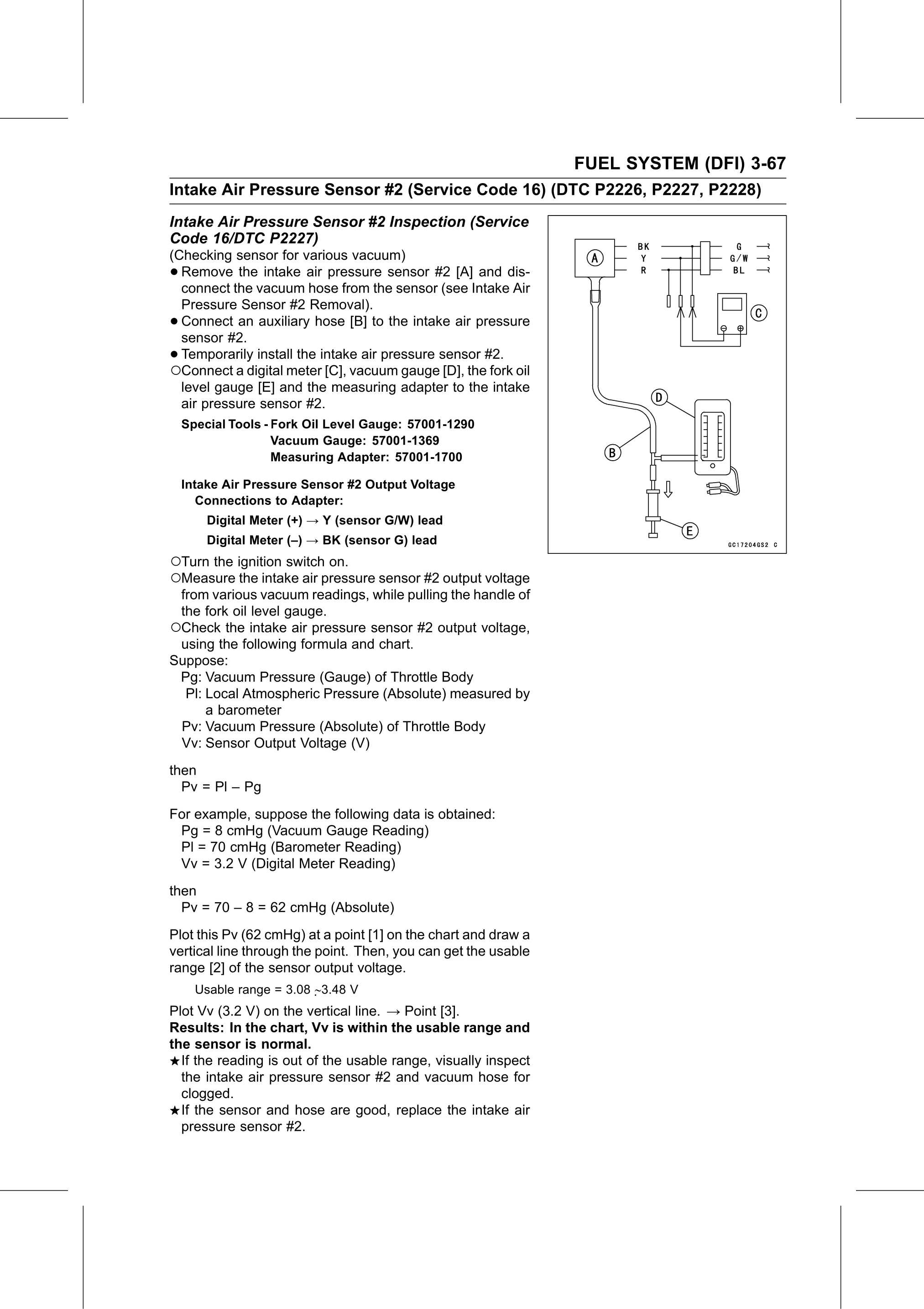
• Remove the intake air pressure sensor #2 [A] and dis-
connect the vacuum hose from the sensor (see Intake Air
Pressure Sensor #2 Removal).
• Connect an auxiliary hose [B] to the intake air pressure
sensor #2.
• Temporarily install the intake air pressure sensor #2.
○Connect a digital meter [C], vacuum gauge [D], the fork oil
level gauge [E] and the measuring adapter to the intake
air pressure sensor #2.
Special Tools - Fork Oil Level Gauge: 57001-1290
Vacuum Gauge: 57001-1369
Measuring Adapter: 57001-1700
Intake Air Pressure Sensor #2 Output Voltage
Connections to Adapter:
Digital Meter (+) → Y (sensor G/W) lead
Digital Meter (–) → BK (sensor G) lead
○Turn the ignition switch on.
○Measure the intake air pressure sensor #2 output voltage
from various vacuum readings, while pulling the handle of
the fork oil level gauge.
○Check the intake air pressure sensor #2 output voltage,
using the following formula and chart.
Suppose:
Pg: Vacuum Pressure (Gauge) of Throttle Body
Pl: Local Atmospheric Pressure (Absolute) measured by
a barometer
Pv: Vacuum Pressure (Absolute) of Throttle Body
Vv: Sensor Output Voltage (V)
then
Pv = Pl – Pg
For example, suppose the following data is obtained:
Pg = 8 cmHg (Vacuum Gauge Reading)
Pl = 70 cmHg (Barometer Reading)
Vv = 3.2 V (Digital Meter Reading)
then
Pv = 70 – 8 = 62 cmHg (Absolute)
Plot this Pv (62 cmHg) at a point [1] on the chart and draw a
vertical line through the point. Then, you can get the usable
range [2] of the sensor output voltage.
Usable range = 3.08 ∼3.48 V
Plot Vv (3.2 V) on the vertical line. → Point [3].
Results: In the chart, Vv is within the usable range and
the sensor is normal.
If the reading is out of the usable range, visually inspect
the intake air pressure sensor #2 and vacuum hose for
clogged.
If the sensor and hose are good, replace the intake air
pressure sensor #2.