Service Manual — page 188 of 715
Fuel System (DFI) › Subthrottle Valve Actuator Inspection
Text on this page
3-98 FUEL SYSTEM (DFI)
Subthrottle Valve Actuator (Service Code 62) (DTC P2100)
(Checking power supply to actuator)
• Connect the ECU connectors.
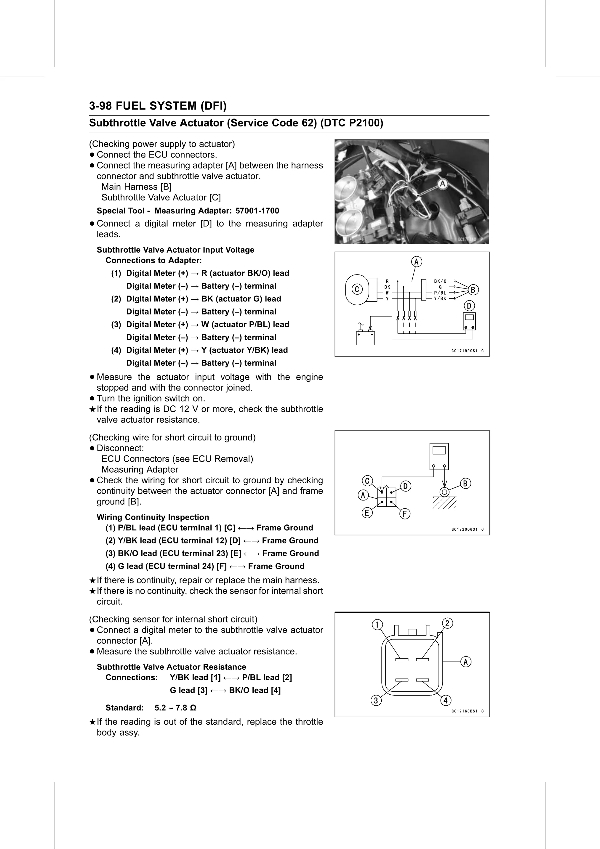
• Connect the measuring adapter [A] between the harness
  connector and subthrottle valve actuator.
   Main Harness [B]
   Subthrottle Valve Actuator [C]
    Special Tool - Measuring Adapter: 57001-1700
• Connect
  leads.
          a digital meter [D] to the measuring adapter

    Subthrottle Valve Actuator Input Voltage
      Connections to Adapter:
       (1) Digital Meter (+) → R (actuator BK/O) lead
            Digital Meter (–) → Battery (–) terminal
       (2) Digital Meter (+) → BK (actuator G) lead
            Digital Meter (–) → Battery (–) terminal
       (3) Digital Meter (+) → W (actuator P/BL) lead
            Digital Meter (–) → Battery (–) terminal
       (4) Digital Meter (+) → Y (actuator Y/BK) lead
            Digital Meter (–) → Battery (–) terminal

• Measure     the actuator input voltage with the engine
  stopped and with the connector joined.
• Turn  the ignition switch on.
  If the reading is DC 12 V or more, check the subthrottle
    valve actuator resistance.
(Checking wire for short circuit to ground)
• Disconnect:
   ECU Connectors (see ECU Removal)
   Measuring Adapter
• Check the wiring for short circuit to ground by checking
  continuity between the actuator connector [A] and frame
  ground [B].
    Wiring Continuity Inspection
     (1) P/BL lead (ECU terminal 1) [C] ←→ Frame Ground
      (2) Y/BK lead (ECU terminal 12) [D] ←→ Frame Ground
      (3) BK/O lead (ECU terminal 23) [E] ←→ Frame Ground
      (4) G lead (ECU terminal 24) [F] ←→ Frame Ground
    If there is continuity, repair or replace the main harness.
    If there is no continuity, check the sensor for internal short
    circuit.
(Checking sensor for internal short circuit)
• Connect a digital meter to the subthrottle valve actuator
  connector [A].
• Measure the subthrottle valve actuator resistance.
    Subthrottle Valve Actuator Resistance
      Connections: Y/BK lead [1] ←→ P/BL lead [2]
                        G lead [3] ←→ BK/O lead [4]

      Standard:    5.2 ∼ 7.8 Ω
    If the reading is out of the standard, replace the throttle
    body assy.