Service Manual — page 194 of 715
Fuel System (DFI) › Purge Valve Operation Inspection
Text on this page
3-104 FUEL SYSTEM (DFI)
Purge Valve (Service Code 3A) (DTC P0443) (Other than US, CA, ID and SEA-B2
Models)
Purge Valve Removal/Installation
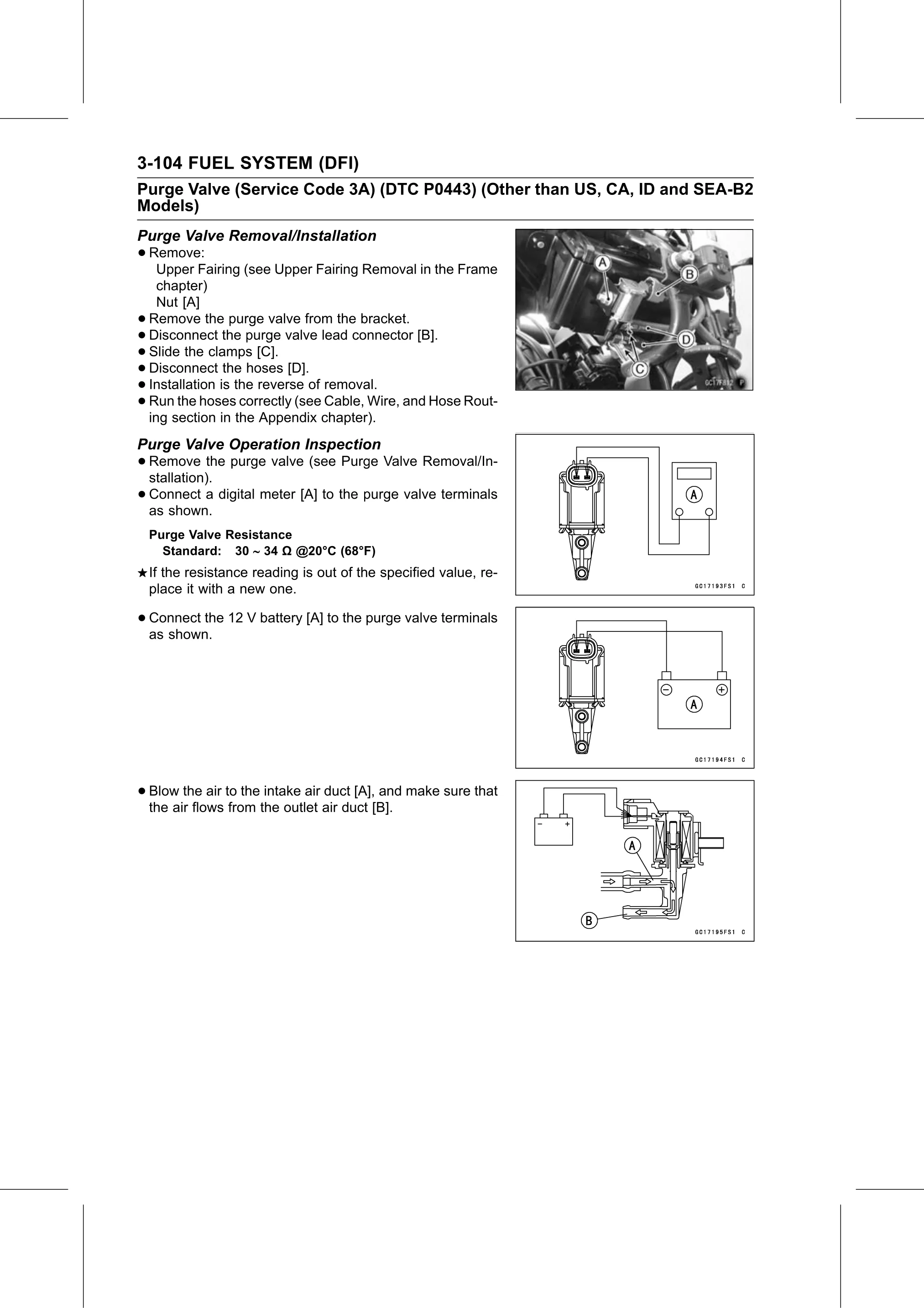
• Remove:
   Upper Fairing (see Upper Fairing Removal in the Frame
      chapter)
      Nut [A]
•   Remove the purge valve from the bracket.
•   Disconnect the purge valve lead connector [B].
•   Slide the clamps [C].
•   Disconnect the hoses [D].
•   Installation is the reverse of removal.
•   Run the hoses correctly (see Cable, Wire, and Hose Rout-
    ing section in the Appendix chapter).
Purge Valve Operation Inspection
• Remove    the purge valve (see Purge Valve Removal/In-
  stallation).
• Connect
  as shown.
            a digital meter [A] to the purge valve terminals

    Purge Valve Resistance
      Standard: 30 ∼ 34 Ω @20°C (68°F)
    If the resistance reading is out of the specified value, re-
    place it with a new one.

• Connect the 12 V battery [A] to the purge valve terminals
  as shown.

• Blow  the air to the intake air duct [A], and make sure that
  the air flows from the outlet air duct [B].