Service Manual — page 363 of 715
Crankshaft/Transmission › Connecting Rod Installation
Text on this page
CRANKSHAFT/TRANSMISSION 9-17
Crankshaft and Connecting Rods
Connecting Rod Installation
                           NOTICE
    To minimize vibration, the connecting rods should
    have the same weight mark.
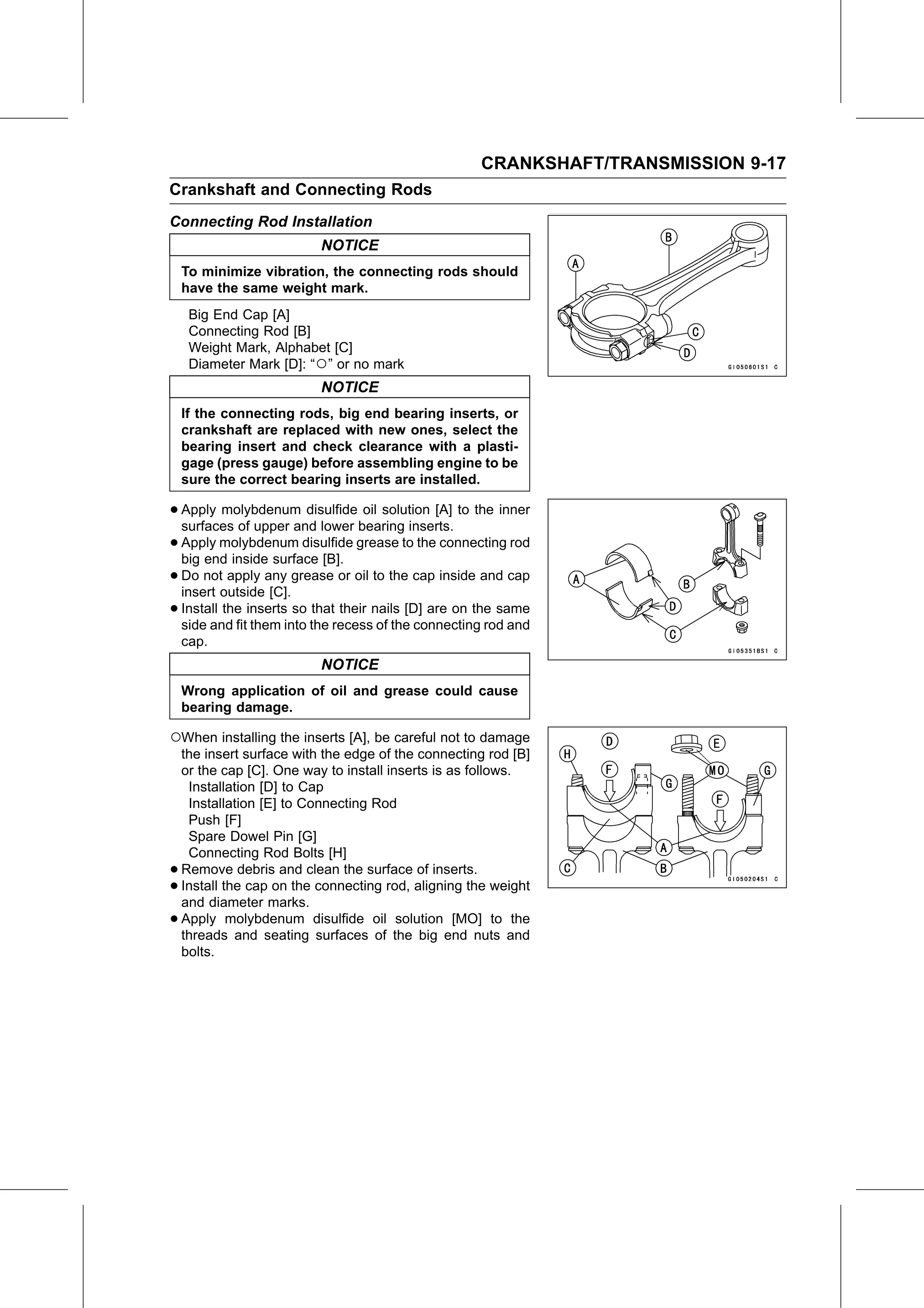
     Big End Cap [A]
     Connecting Rod [B]
     Weight Mark, Alphabet [C]
     Diameter Mark [D]: “○” or no mark
                           NOTICE
    If the connecting rods, big end bearing inserts, or
    crankshaft are replaced with new ones, select the
    bearing insert and check clearance with a plasti-
    gage (press gauge) before assembling engine to be
    sure the correct bearing inserts are installed.

• Apply   molybdenum disulfide oil solution [A] to the inner
  surfaces of upper and lower bearing inserts.
• Apply   molybdenum disulfide grease to the connecting rod
  big end inside surface [B].
• Do  not apply any grease or oil to the cap inside and cap
  insert outside [C].
• Install the inserts so that their nails [D] are on the same
  side and fit them into the recess of the connecting rod and
    cap.
                           NOTICE
    Wrong application of oil and grease could cause
    bearing damage.

○When installing the inserts [A], be careful not to damage
    the insert surface with the edge of the connecting rod [B]
    or the cap [C]. One way to install inserts is as follows.
     Installation [D] to Cap
     Installation [E] to Connecting Rod
     Push [F]
     Spare Dowel Pin [G]
     Connecting Rod Bolts [H]
•   Remove debris and clean the surface of inserts.
•   Install the cap on the connecting rod, aligning the weight
    and diameter marks.
•   Apply molybdenum disulfide oil solution [MO] to the
    threads and seating surfaces of the big end nuts and
    bolts.