Service Manual — page 443 of 715
Brakes › Brake Disc Warp
Text on this page
BRAKES 12-21
Brake Disc
Brake Disc Removal
• Remove  the wheels (see Front/Rear Wheel Removal in
  the Wheels/Tires chapter).
• Unscrew the mounting bolts [A], and take off the disc [B].
• Remove  the gaskets (Front Only).

Brake Disc Installation
• Replace    the gaskets with new ones (Front Only).
• Install the brake disc on the wheel so that the marked side
  [A] faces out.
• Apply   a non-permanent locking agent to the threads of
  the front and rear brake disc mounting bolts, and tighten
    them.
    Torque - Brake Disc Mounting Bolts: 28 N·m (2.9 kgf·m, 21
                ft·lb)

Brake Disc Wear
• Measure  the thickness of each disc [A] at the point where
  it has worn the most.
    If the disc has worn past the service limit, replace it.
      Measuring Area [B]
    Brake Discs Thickness
      Standard:
        Front          4.8 ∼ 5.2 mm (0.19 ∼ 0.20 in.)
        Rear           5.8 ∼ 6.2 mm (0.23 ∼ 0.24 in.)
      Service Limit:
        Front          4.5 mm (0.18 in.)
        Rear           5.5 mm (0.22 in.)

Brake Disc Warp
• Raise the front/rear wheel off the ground.
    Special Tools - Jack: 57001-1238
                    Attachment Jack: 57001-1252
                    Jack Attachment: 57001-1608
○For front disc inspection, turn the handlebars fully to one
    side.
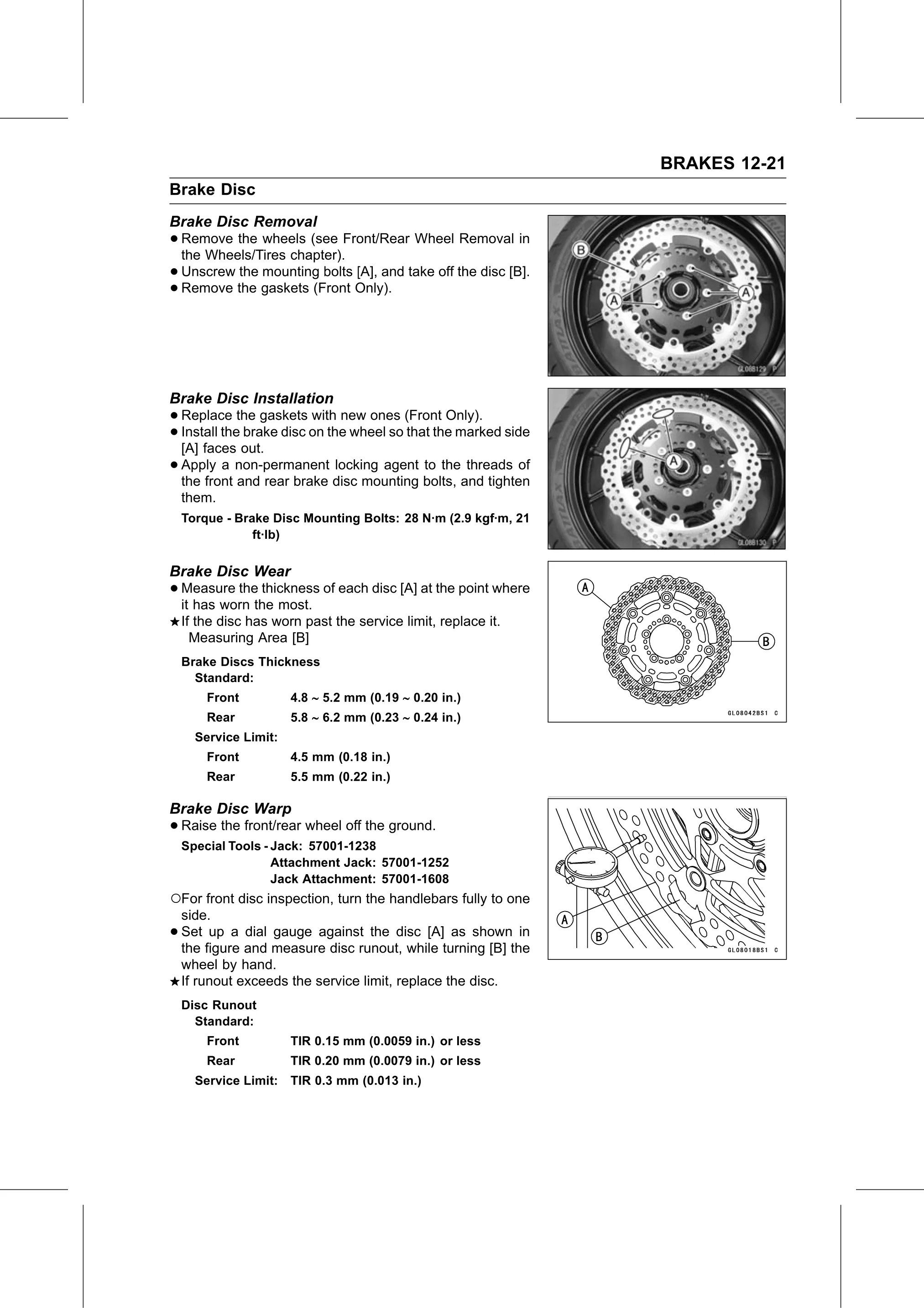
•   Set up a dial gauge against the disc [A] as shown in
    the figure and measure disc runout, while turning [B] the
    wheel by hand.
    If runout exceeds the service limit, replace the disc.
    Disc Runout
      Standard:
        Front          TIR 0.15 mm (0.0059 in.) or less
        Rear           TIR 0.20 mm (0.0079 in.) or less
      Service Limit:   TIR 0.3 mm (0.013 in.)