Service Manual — page 451 of 715
Brakes › Parts Location
Text on this page
BRAKES 12-29
Anti-Lock Brake System
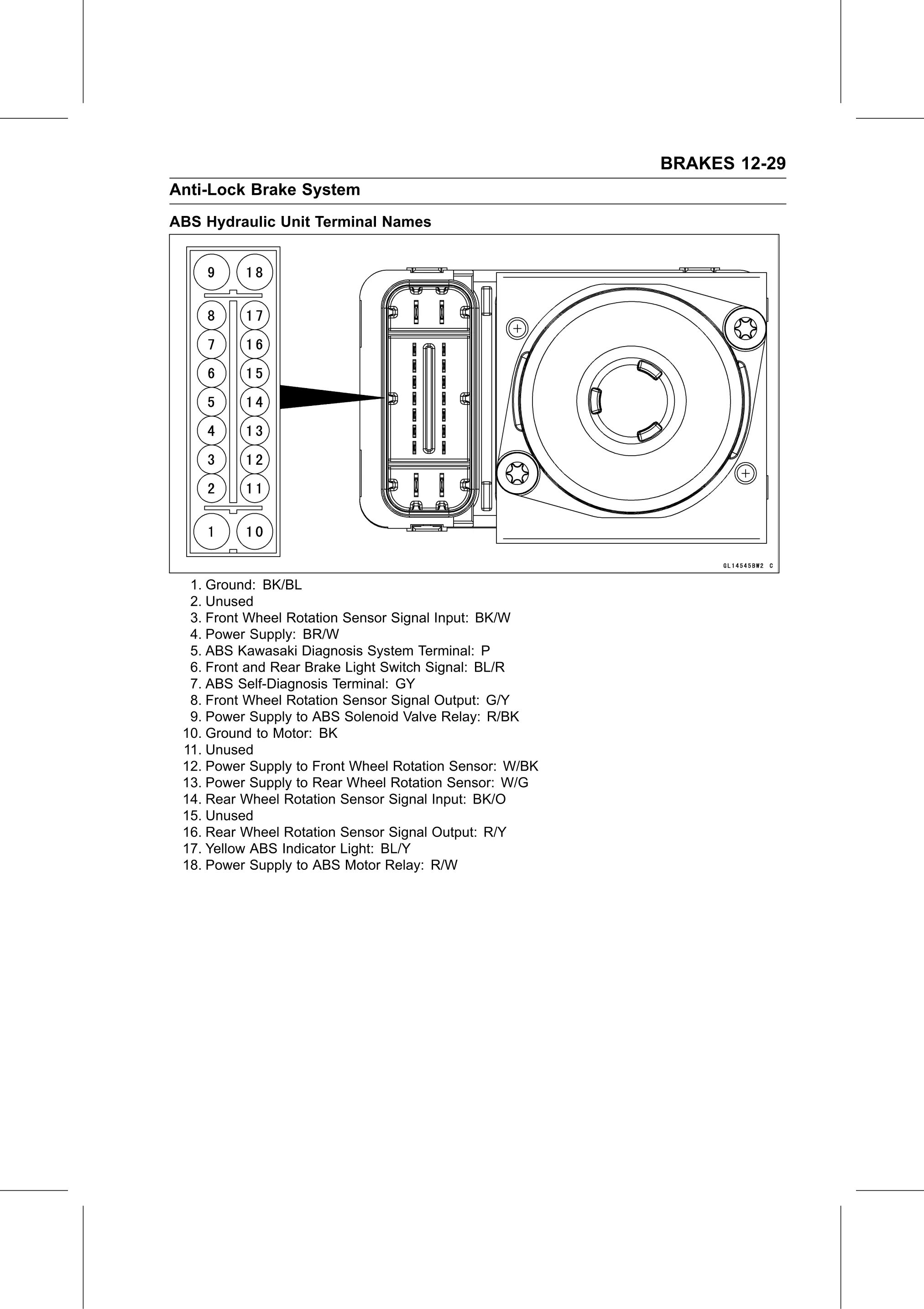
ABS Hydraulic Unit Terminal Names

  1. Ground: BK/BL
  2. Unused
  3. Front Wheel Rotation Sensor Signal Input: BK/W
  4. Power Supply: BR/W
  5. ABS Kawasaki Diagnosis System Terminal: P
  6. Front and Rear Brake Light Switch Signal: BL/R
  7. ABS Self-Diagnosis Terminal: GY
  8. Front Wheel Rotation Sensor Signal Output: G/Y
  9. Power Supply to ABS Solenoid Valve Relay: R/BK
 10. Ground to Motor: BK
 11. Unused
 12. Power Supply to Front Wheel Rotation Sensor: W/BK
 13. Power Supply to Rear Wheel Rotation Sensor: W/G
 14. Rear Wheel Rotation Sensor Signal Input: BK/O
 15. Unused
 16. Rear Wheel Rotation Sensor Signal Output: R/Y
 17. Yellow ABS Indicator Light: BL/Y
 18. Power Supply to ABS Motor Relay: R/W