Service Manual — page 662 of 715
Electrical System › Immobilizer System Parts Replacement
Text on this page
16-102 ELECTRICAL SYSTEM
Immobilizer System (Equipped Models)
Immobilizer System Parts Replacement
Ignition Switch (Immobilizer Antenna) Replacement
• Remove:
   Left Side Cover (see Side Cover Removal in the Frame
   chapter)
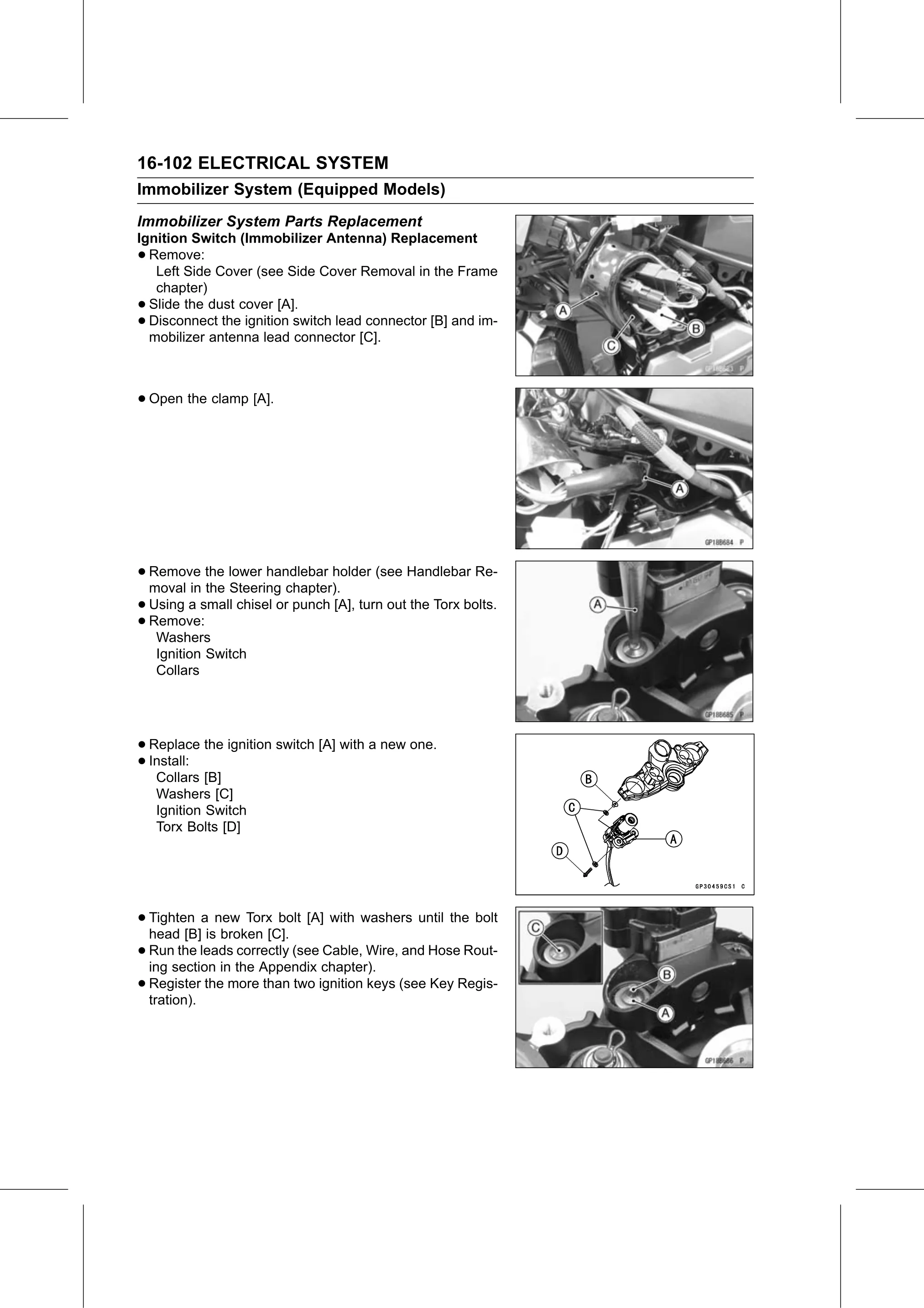
• Slide the dust cover [A].
• Disconnect the ignition switch lead connector [B] and im-
  mobilizer antenna lead connector [C].

• Open the clamp [A].

• Remove   the lower handlebar holder (see Handlebar Re-
  moval in the Steering chapter).
• Using a small chisel or punch [A], turn out the Torx bolts.
• Washers
  Remove:

    Ignition Switch
    Collars

• Replace  the ignition switch [A] with a new one.
• Install:
   Collars [B]
    Washers [C]
    Ignition Switch
    Torx Bolts [D]

• Tighten   a new Torx bolt [A] with washers until the bolt
  head [B] is broken [C].
• Run   the leads correctly (see Cable, Wire, and Hose Rout-
  ing section in the Appendix chapter).
• Register
  tration).
             the more than two ignition keys (see Key Regis-