Service Manual — page 667 of 715
Electrical System › Outside Temperature Sensor Installation
Text on this page
ELECTRICAL SYSTEM 16-107
Switches and Sensors
Oxygen Sensor Installation
                          NOTICE
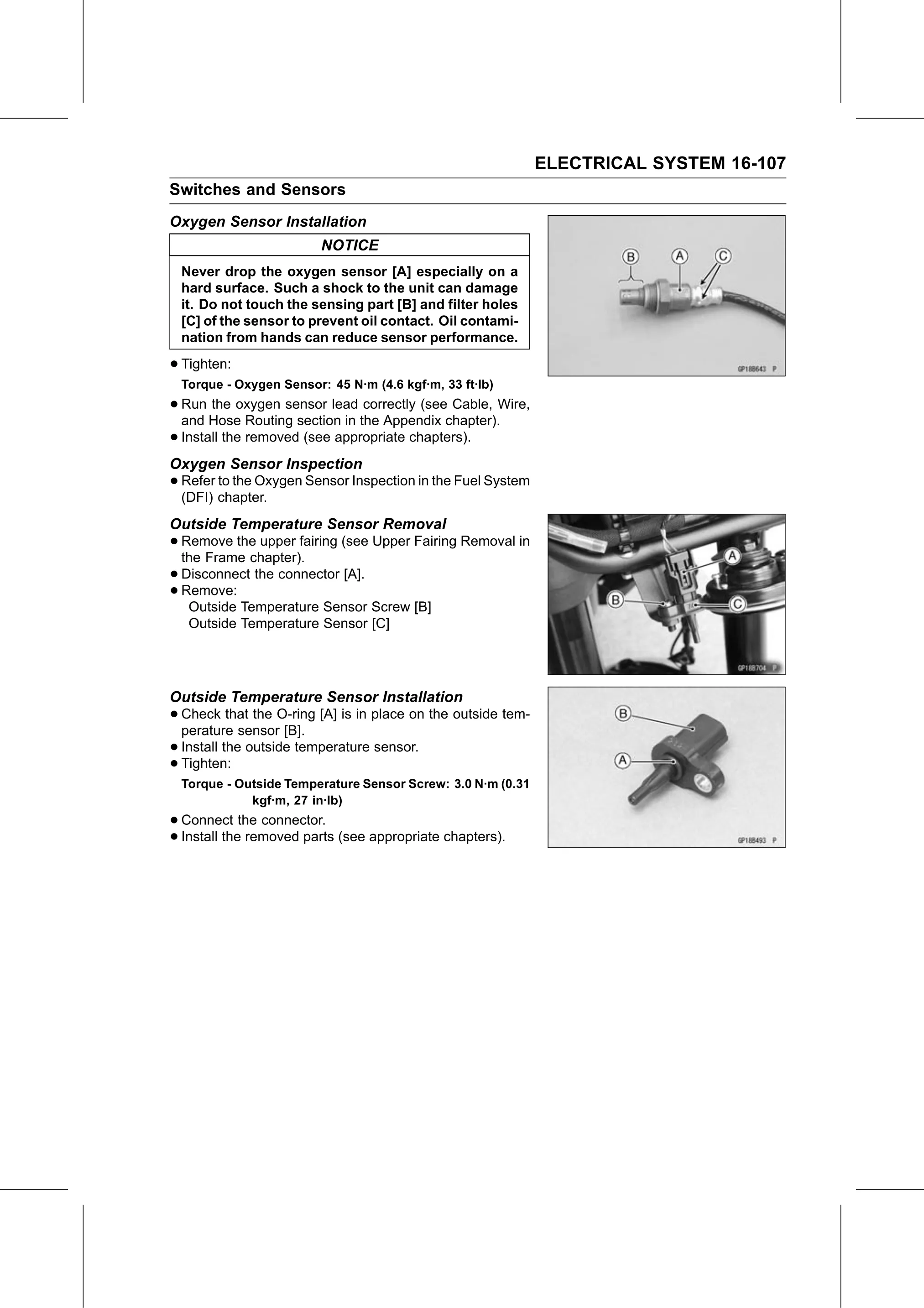
  Never drop the oxygen sensor [A] especially on a
  hard surface. Such a shock to the unit can damage
  it. Do not touch the sensing part [B] and filter holes
  [C] of the sensor to prevent oil contact. Oil contami-
  nation from hands can reduce sensor performance.

• Tighten:
  Torque - Oxygen Sensor: 45 N·m (4.6 kgf·m, 33 ft·lb)
• Run  the oxygen sensor lead correctly (see Cable, Wire,
  and Hose Routing section in the Appendix chapter).
• Install the removed (see appropriate chapters).
Oxygen Sensor Inspection
• Refer to the Oxygen Sensor Inspection in the Fuel System
  (DFI) chapter.
Outside Temperature Sensor Removal
• Remove  the upper fairing (see Upper Fairing Removal in
  the Frame chapter).
• Disconnect the connector [A].
• Outside Temperature Sensor Screw [B]
  Remove:

   Outside Temperature Sensor [C]

Outside Temperature Sensor Installation
• Check    that the O-ring [A] is in place on the outside tem-
  perature sensor [B].
• Install the outside temperature sensor.
• Tighten:
  Torque - Outside Temperature Sensor Screw: 3.0 N·m (0.31
             kgf·m, 27 in·lb)
• Connect    the connector.
• Install the removed parts (see appropriate chapters).