Service Manual (KLZ1000C) — page 387 of 762
Brakes › Front Wheel Rotation Sensor Removal
Text on this page
BRAKES 12-47
Anti-Lock Brake System

• Pull the lever [A] backward to connect the ABS hydraulic
  unit connector [B].

• Apply   a non-permanent locking agent to the thread of the
  bolts [A], and tighten them.
• Install  the brake hoses correctly (see Brake Hose and
  Pipe Replacement(2-44)).
• Bleed   the brake line (see Brake Line Bleeding(12-26)).
• and nothe
  Check          brake for good braking power, no brake drag,
            fluid leakage.
• Install the   removed parts.

ABS Hydraulic Unit Inspection
• Remove    the ABS hydraulic unit (see ABS Hydraulic Unit
  Removal(12-45)).
• Visually inspect the ABS hydraulic unit.
  Replace the ABS hydraulic unit if any of them are cracked,
  or otherwise damaged.

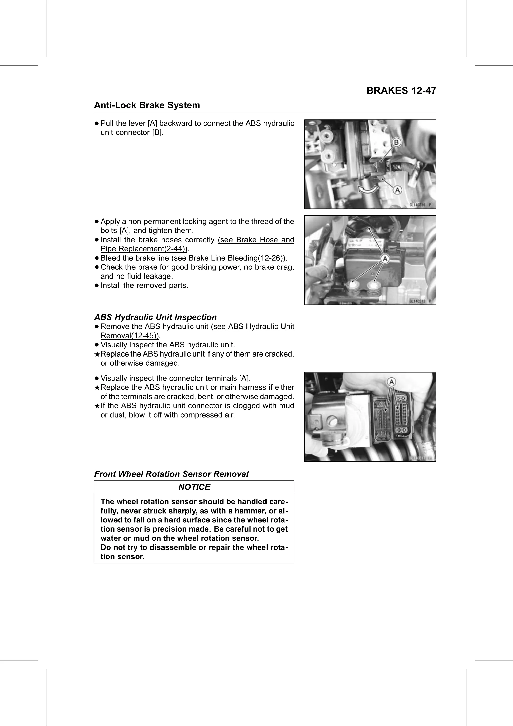
• Visually inspect the connector terminals [A].
  Replace the ABS hydraulic unit or main harness if either
  of the terminals are cracked, bent, or otherwise damaged.
  If the ABS hydraulic unit connector is clogged with mud
  or dust, blow it off with compressed air.

Front Wheel Rotation Sensor Removal
                         NOTICE
  The wheel rotation sensor should be handled care-
  fully, never struck sharply, as with a hammer, or al-
  lowed to fall on a hard surface since the wheel rota-
  tion sensor is precision made. Be careful not to get
  water or mud on the wheel rotation sensor.
  Do not try to disassemble or repair the wheel rota-
  tion sensor.