Service Manual (KLZ1000C) — page 518 of 762
Electrical System › Charging Voltage Inspection
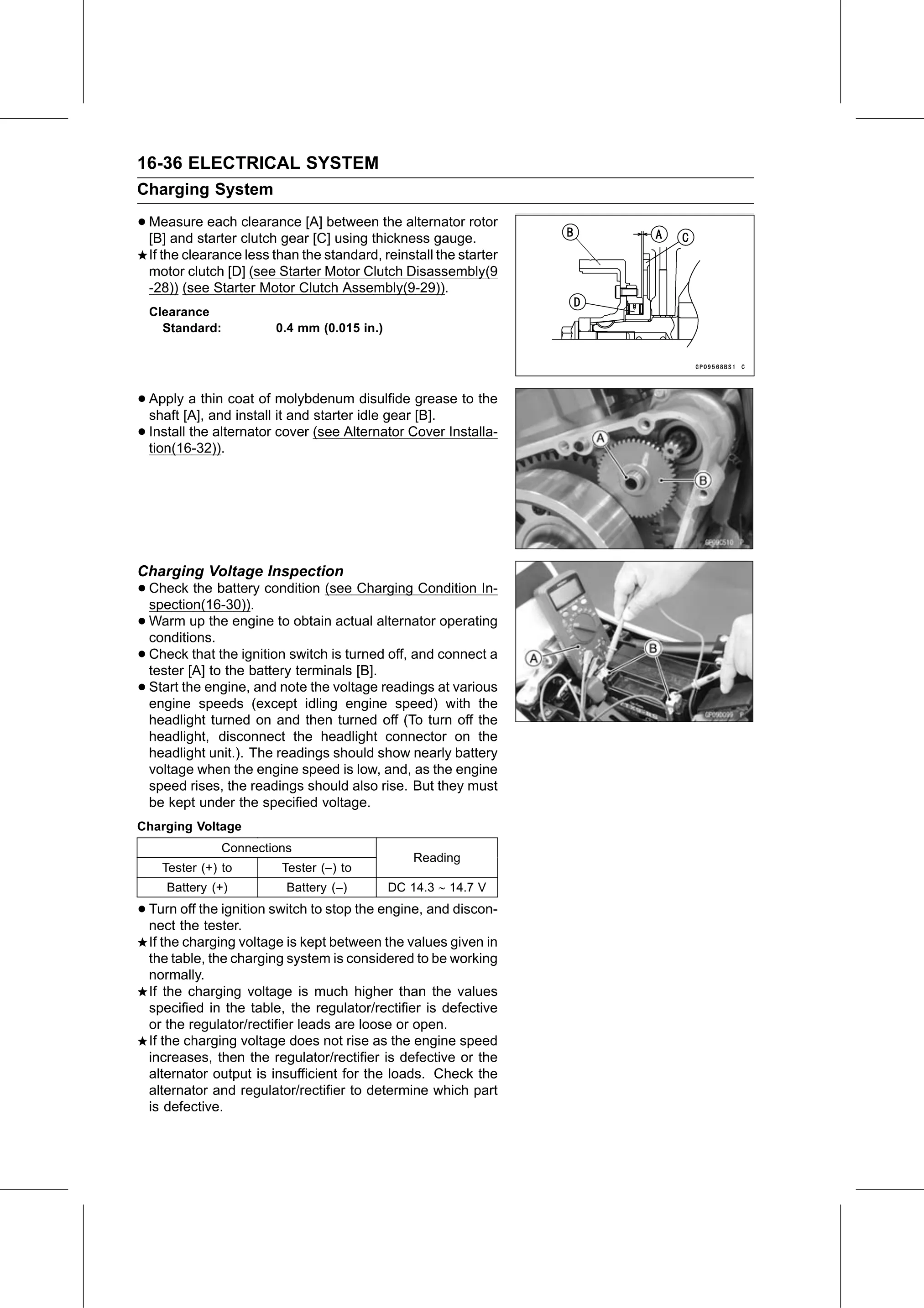
Text on this page
16-36 ELECTRICAL SYSTEM
Charging System
• Measure each clearance [A] between the alternator rotor
[B] and starter clutch gear [C] using thickness gauge.
If the clearance less than the standard, reinstall the starter
motor clutch [D] (see Starter Motor Clutch Disassembly(9
-28)) (see Starter Motor Clutch Assembly(9-29)).
Clearance
Standard: 0.4 mm (0.015 in.)
• Apply a thin coat of molybdenum disulfide grease to the
shaft [A], and install it and starter idle gear [B].
• Install the alternator cover (see Alternator Cover Installa-
tion(16-32)).
Charging Voltage Inspection
• Check the battery condition (see Charging Condition In-
spection(16-30)).
• Warm up the engine to obtain actual alternator operating
conditions.
• Check that the ignition switch is turned off, and connect a
tester [A] to the battery terminals [B].
• Start the engine, and note the voltage readings at various
engine speeds (except idling engine speed) with the
headlight turned on and then turned off (To turn off the
headlight, disconnect the headlight connector on the
headlight unit.). The readings should show nearly battery
voltage when the engine speed is low, and, as the engine
speed rises, the readings should also rise. But they must
be kept under the specified voltage.
Charging Voltage
Connections
Reading
Tester (+) to Tester (–) to
Battery (+) Battery (–) DC 14.3 14.7 V
• Turn off the ignition switch to stop the engine, and discon-
nect the tester.
If the charging voltage is kept between the values given in
the table, the charging system is considered to be working
normally.
If the charging voltage is much higher than the values
specified in the table, the regulator/rectifier is defective
or the regulator/rectifier leads are loose or open.
If the charging voltage does not rise as the engine speed
increases, then the regulator/rectifier is defective or the
alternator output is insufficient for the loads. Check the
alternator and regulator/rectifier to determine which part
is defective.