Service Manual (KLZ1000C) — page 519 of 762
Electrical System › Alternator Inspection
Text on this page
ELECTRICAL SYSTEM 16-37
Charging System
Alternator Inspection
There are three types of alternator failures: short, open
(wire burned out), or loss in rotor magnetism. A short or
open in one of the coil wires will result in either a low output,
or no output at all. A loss in rotor magnetism, which may be
caused by dropping or hitting the alternator, by leaving it
near an electromagnetic field, or just by aging, will result in
low output.
• To check the alternator output voltage, do the following
procedures.
○Turn the ignition switch off.
○Remove the left inner middle fairing (see Inner Middle
Fairing Removal(15-15)).
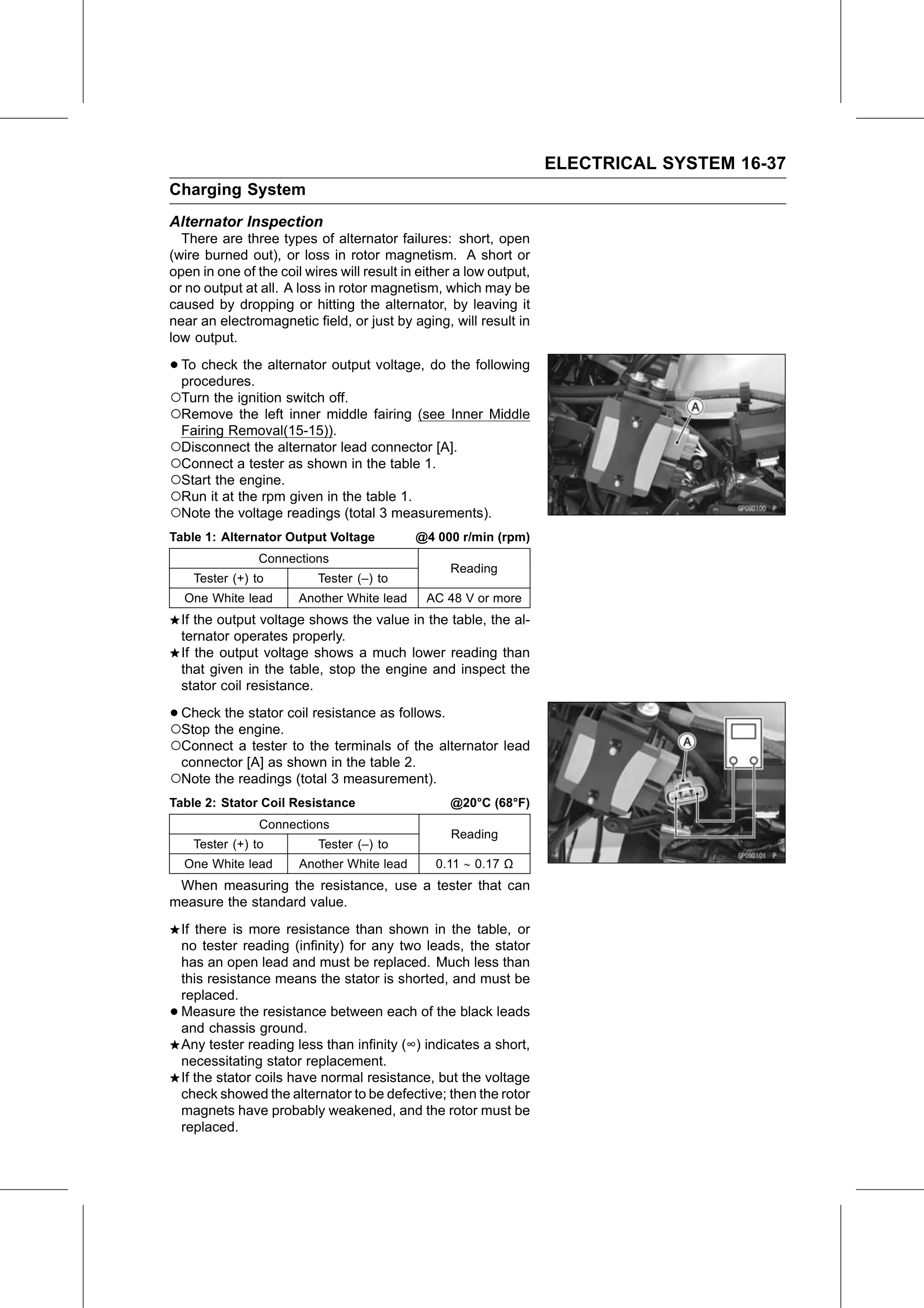
○Disconnect the alternator lead connector [A].
○Connect a tester as shown in the table 1.
○Start the engine.
○Run it at the rpm given in the table 1.
○Note the voltage readings (total 3 measurements).
Table 1: Alternator Output Voltage @4 000 r/min (rpm)
Connections
Reading
Tester (+) to Tester (–) to
One White lead Another White lead AC 48 V or more
If the output voltage shows the value in the table, the al-
ternator operates properly.
If the output voltage shows a much lower reading than
that given in the table, stop the engine and inspect the
stator coil resistance.
•○Check the stator coil resistance as follows.
Stop the engine.
○Connect a tester to the terminals of the alternator lead
connector [A] as shown in the table 2.
○Note the readings (total 3 measurement).
Table 2: Stator Coil Resistance @20°C (68°F)
Connections
Reading
Tester (+) to Tester (–) to
One White lead Another White lead 0.11 0.17 Ω
When measuring the resistance, use a tester that can
measure the standard value.
If there is more resistance than shown in the table, or
no tester reading (infinity) for any two leads, the stator
has an open lead and must be replaced. Much less than
this resistance means the stator is shorted, and must be
replaced.
• Measure the resistance between each of the black leads
and chassis ground.
Any tester reading less than infinity (∞) indicates a short,
necessitating stator replacement.
If the stator coils have normal resistance, but the voltage
check showed the alternator to be defective; then the rotor
magnets have probably weakened, and the rotor must be
replaced.