Service Manual (KLZ1000C) — page 644 of 762
Self-Diagnosis System › Crankshaft Sensor Circuit
Text on this page
17-42 SELF-DIAGNOSIS SYSTEM
Crankshaft Sensor (Service Code 21) (DTC P0335)
  When the engine stops, the crankshaft sensor generates
no signals.
Crankshaft Sensor Removal/Installation
• Refer to the Crankshaft Sensor Removal/Installation (see
  Crankshaft Sensor Removal(16-42)) (see Crankshaft
 Sensor Installation(16-43)).
Crankshaft Sensor Resistance Inspection
• Refer  to the Crankshaft Sensor Inspection (see Crank-
  shaft Sensor Inspection(16-45)).
 If the reading is within the standard, check the peak volt-
 age (see Crankshaft Sensor Peak Voltage Inspection(17
 -42)).
Crankshaft Sensor Peak Voltage Inspection
• Refer to the Crankshaft Sensor Peak Voltage Inspection
  (see Crankshaft Sensor Peak Voltage Inspection(16-45)).
 If the reading is within the standard, remove the ECU and
 check the wiring for continuity between harness connec-
 tors.
○Disconnect the ECU and sensor connectors.
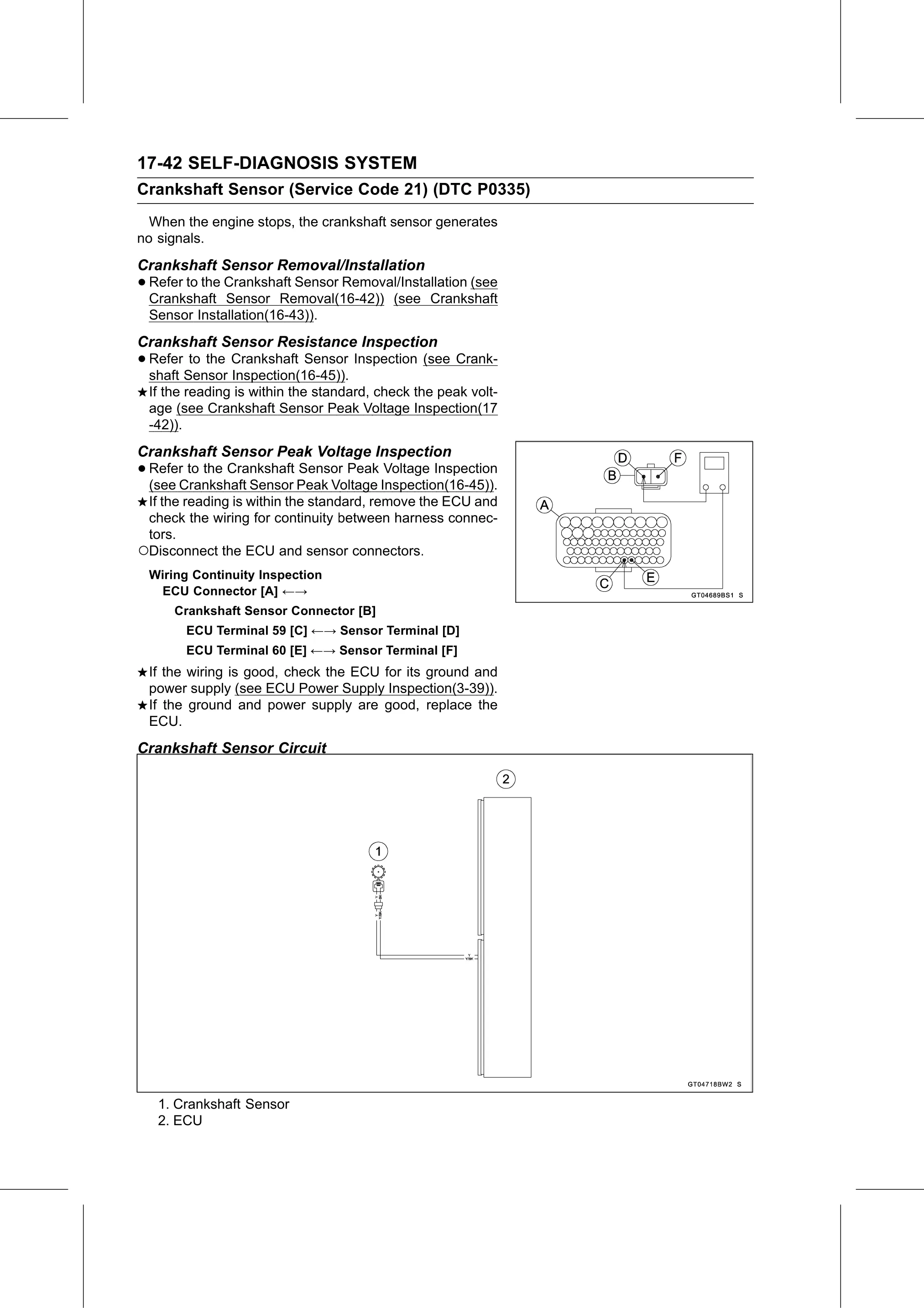
 Wiring Continuity Inspection
  ECU Connector [A] ←→
      Crankshaft Sensor Connector [B]
       ECU Terminal 59 [C] ←→ Sensor Terminal [D]
       ECU Terminal 60 [E] ←→ Sensor Terminal [F]
 If the wiring is good, check the ECU for its ground and
 power supply (see ECU Power Supply Inspection(3-39)).
 If the ground and power supply are good, replace the
 ECU.
Crankshaft Sensor Circuit

   1. Crankshaft Sensor
   2. ECU