Service Manual (KLZ1000C) — page 648 of 762
Self-Diagnosis System › Gear Position Sensor Output Voltage Inspection
Text on this page
17-46 SELF-DIAGNOSIS SYSTEM
Gear Position Sensor (Service Code 25) (DTC P0914, P0916)
Gear Position Sensor Output Voltage Inspection
• Measure the output voltage at the gear position sensor in
the same way as input voltage inspection, note the follow-
ing.
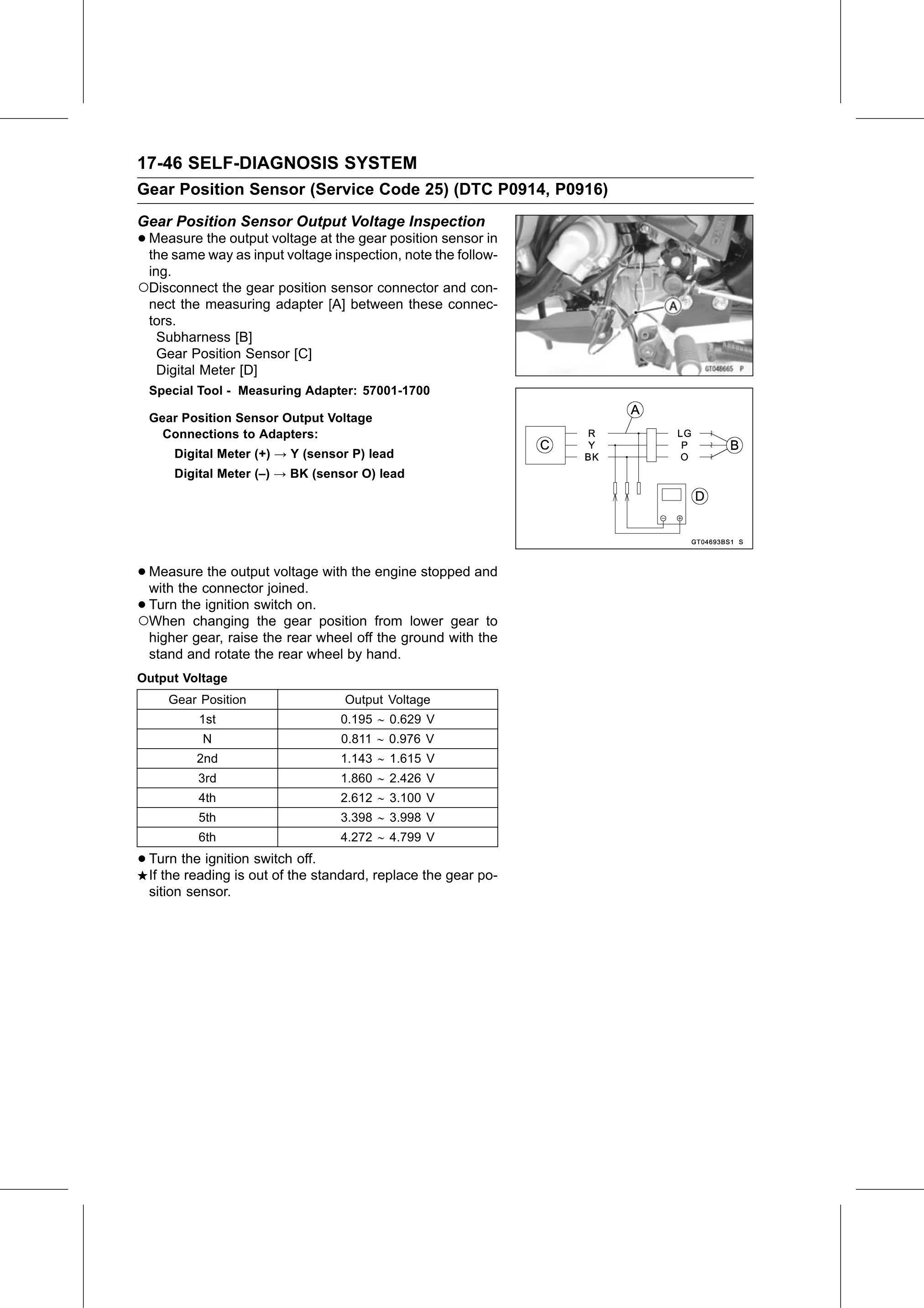
○Disconnect the gear position sensor connector and con-
nect the measuring adapter [A] between these connec-
tors.
Subharness [B]
Gear Position Sensor [C]
Digital Meter [D]
Special Tool - Measuring Adapter: 57001-1700
Gear Position Sensor Output Voltage
Connections to Adapters:
Digital Meter (+) → Y (sensor P) lead
Digital Meter (–) → BK (sensor O) lead
• Measure the output voltage with the engine stopped and
with the connector joined.
•○Turn the ignition switch on.
When changing the gear position from lower gear to
higher gear, raise the rear wheel off the ground with the
stand and rotate the rear wheel by hand.
Output Voltage
Gear Position Output Voltage
1st 0.195 0.629 V
N 0.811 0.976 V
2nd 1.143 1.615 V
3rd 1.860 2.426 V
4th 2.612 3.100 V
5th 3.398 3.998 V
6th 4.272 4.799 V
• Turn the ignition switch off.
If the reading is out of the standard, replace the gear po-
sition sensor.