Service Manual (KLZ1000C) — page 660 of 762
Self-Diagnosis System › Amplifier Input Voltage Inspection
Text on this page
17-58 SELF-DIAGNOSIS SYSTEM
Immobilizer Amplifier (Service Code 35, Equipped Models) (DTC P1507)
Antenna Resistance Inspection
• Turn the ignition switch off.
• Remove:
Left Inner Middle Fairing (see Inner Middle Fairing Re-
moval(15-15))
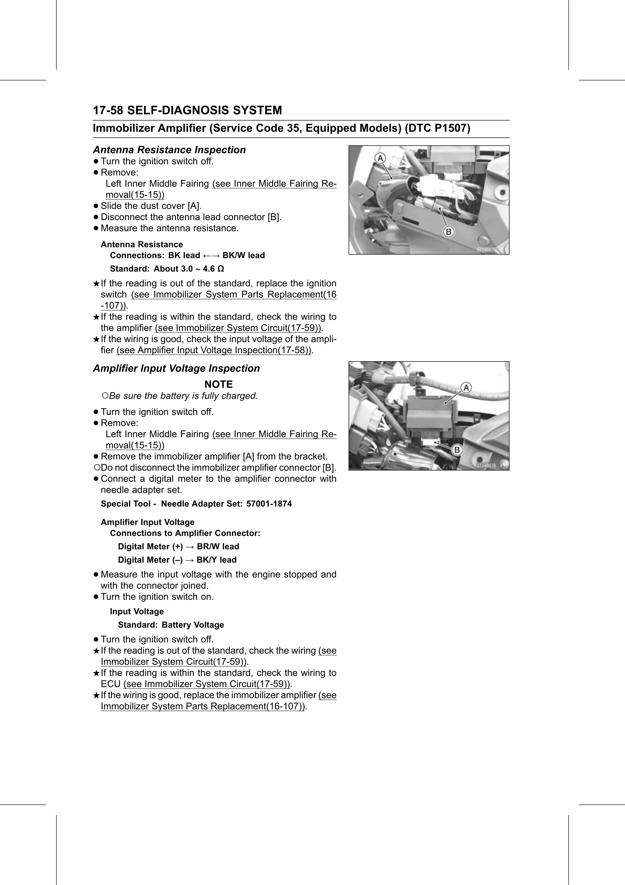
• Slide the dust cover [A].
• Disconnect the antenna lead connector [B].
• Measure the antenna resistance.
Antenna Resistance
Connections: BK lead ←→ BK/W lead
Standard: About 3.0 4.6 Ω
If the reading is out of the standard, replace the ignition
switch (see Immobilizer System Parts Replacement(16
-107)).
If the reading is within the standard, check the wiring to
the amplifier (see Immobilizer System Circuit(17-59)).
If the wiring is good, check the input voltage of the ampli-
fier (see Amplifier Input Voltage Inspection(17-58)).
Amplifier Input Voltage Inspection
NOTE
○Be sure the battery is fully charged.
• Turn the ignition switch off.
• Remove:
Left Inner Middle Fairing (see Inner Middle Fairing Re-
moval(15-15))
•Remove the immobilizer amplifier [A] from the bracket.
○Do not disconnect the immobilizer amplifier connector [B].
•Connect a digital meter to the amplifier connector with
needle adapter set.
Special Tool - Needle Adapter Set: 57001-1874
Amplifier Input Voltage
Connections to Amplifier Connector:
Digital Meter (+) → BR/W lead
Digital Meter (–) → BK/Y lead
• Measure the input voltage with the engine stopped and
with the connector joined.
• Turn the ignition switch on.
Input Voltage
Standard: Battery Voltage
• Turn the ignition switch off.
If the reading is out of the standard, check the wiring (see
Immobilizer System Circuit(17-59)).
If the reading is within the standard, check the wiring to
ECU (see Immobilizer System Circuit(17-59)).
If the wiring is good, replace the immobilizer amplifier (see
Immobilizer System Parts Replacement(16-107)).