Service Manual (KLZ1000C) — page 687 of 762
Self-Diagnosis System › IMU Power Supply Inspection
Text on this page
SELF-DIAGNOSIS SYSTEM 17-85
IMU (Inertial Measurement Unit) (Service Code E8E)
IMU Removal
                          NOTICE
  Never drop the IMU especially on a hard surface.
  Such a shock to the sensor can damage it.

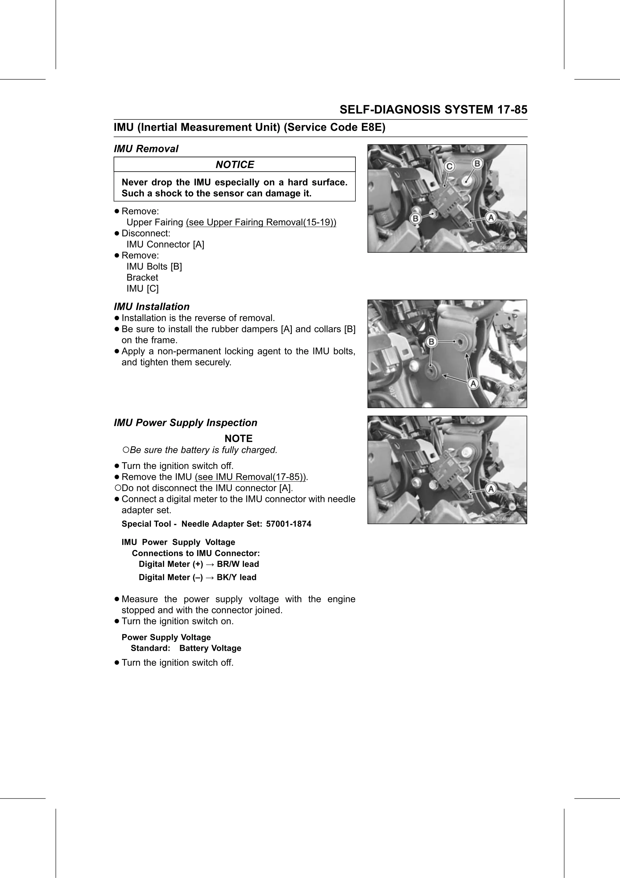
• Remove:
   Upper Fairing (see Upper Fairing Removal(15-19))
• IMU Connector [A]
  Disconnect:

• Remove:
   IMU Bolts [B]
   Bracket
   IMU [C]
IMU Installation
• Installation is the reverse of removal.
• on the frame. the rubber dampers [A] and collars [B]
  Be  sure  to install

• Apply  a non-permanent locking agent to the IMU bolts,
  and tighten them securely.

IMU Power Supply Inspection
                            NOTE
  ○Be sure the battery is fully charged.
• Turn the ignition switch off.
•○Remove    the IMU (see IMU Removal(17-85)).
   Do not disconnect the IMU connector [A].
 • Connect  a digital meter to the IMU connector with needle
   adapter set.
  Special Tool - Needle Adapter Set: 57001-1874

  IMU Power Supply Voltage
    Connections to IMU Connector:
     Digital Meter (+) → BR/W lead
      Digital Meter (–) → BK/Y lead

• Measure    the power supply voltage with the engine
  stopped and with the connector joined.
• Turn the ignition switch on.
  Power Supply Voltage
    Standard: Battery Voltage

• Turn the ignition switch off.