Service Manual — page 119 of 715
Fuel System (DFI) › Outline
Text on this page
FUEL SYSTEM (DFI) 3-29
Troubleshooting the DFI System
  Even when the DFI system is operating normally, the yel-
low engine warning indicator light (LED) goes on may be
displayed under strong electrical interference. Additional
measures are not required. Turn the ignition switch off to
stop the indicator.
  If the yellow engine warning indicator light (LED) of the
motorcycle brought in for repair still goes on, check the ser-
vice code.
  When the repair has been done, the yellow engine warn-
ing indicator light (LED) goes off after starting the engine.
But the service codes stored in memory of the ECU are not
erased to preserve the problem history. The problem his-
tory can be referred using the KDS (Kawasaki Diagnostic
System) when solving unstable problems or other proce-
dures (see Service Code Erasing).
  When the motorcycle is down, the vehicle-down sensor
operates and the ECU shuts off the fuel pump relay, fuel
injectors and ignition system. The ignition switch is left on. If
the starter button is pushed, the electric starter turns but the
engine does not start. When the starter button is pushed,
the yellow engine warning indicator light (LED) blinks but
the service code is not displayed. To start the engine again,
raise the motorcycle, turn the ignition switch off, and then
on.
  Much of the DFI system troubleshooting work consists
of confirming continuity of the wiring. The DFI parts are
assembled and adjusted with precision, and it is impossible
to disassemble or repair them.

• When  checking the DFI parts, use a digital meter which
  can be read two decimal place voltage or resistance.
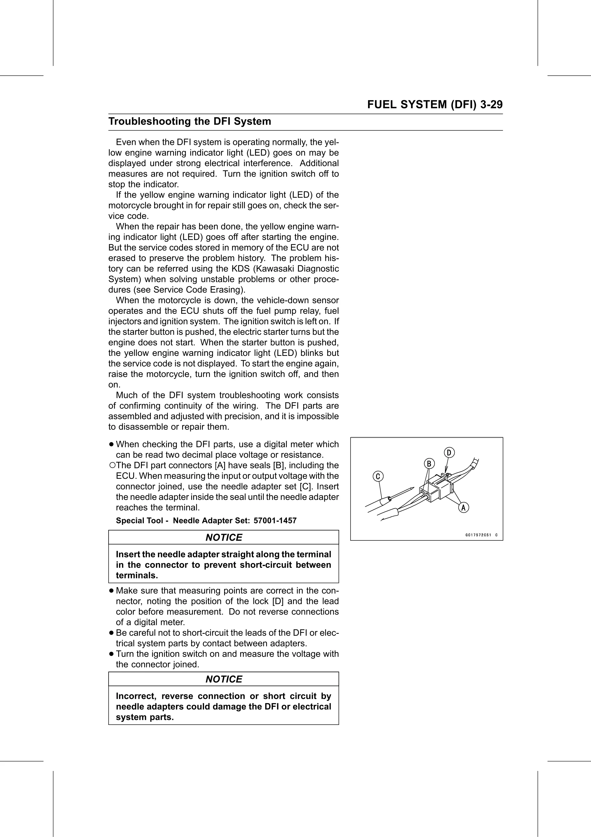
○The DFI part connectors [A] have seals [B], including the
    ECU. When measuring the input or output voltage with the
    connector joined, use the needle adapter set [C]. Insert
    the needle adapter inside the seal until the needle adapter
    reaches the terminal.
    Special Tool - Needle Adapter Set: 57001-1457

                            NOTICE
    Insert the needle adapter straight along the terminal
    in the connector to prevent short-circuit between
    terminals.

• Make  sure that measuring points are correct in the con-
  nector, noting the position of the lock [D] and the lead
    color before measurement. Do not reverse connections
    of a digital meter.
•   Be careful not to short-circuit the leads of the DFI or elec-
    trical system parts by contact between adapters.
•   Turn the ignition switch on and measure the voltage with
    the connector joined.
                            NOTICE
    Incorrect, reverse connection or short circuit by
    needle adapters could damage the DFI or electrical
    system parts.