Service Manual — page 177 of 715
Fuel System (DFI) › Amplifier Input Voltage Inspection
Text on this page
FUEL SYSTEM (DFI) 3-87
Immobilizer Amplifier (Service Code 35, Equipped Models)
Antenna Resistance Inspection
• Turn the ignition switch off.
• Remove   the left side cover (see Side Cover Removal in
  the Frame chapter).

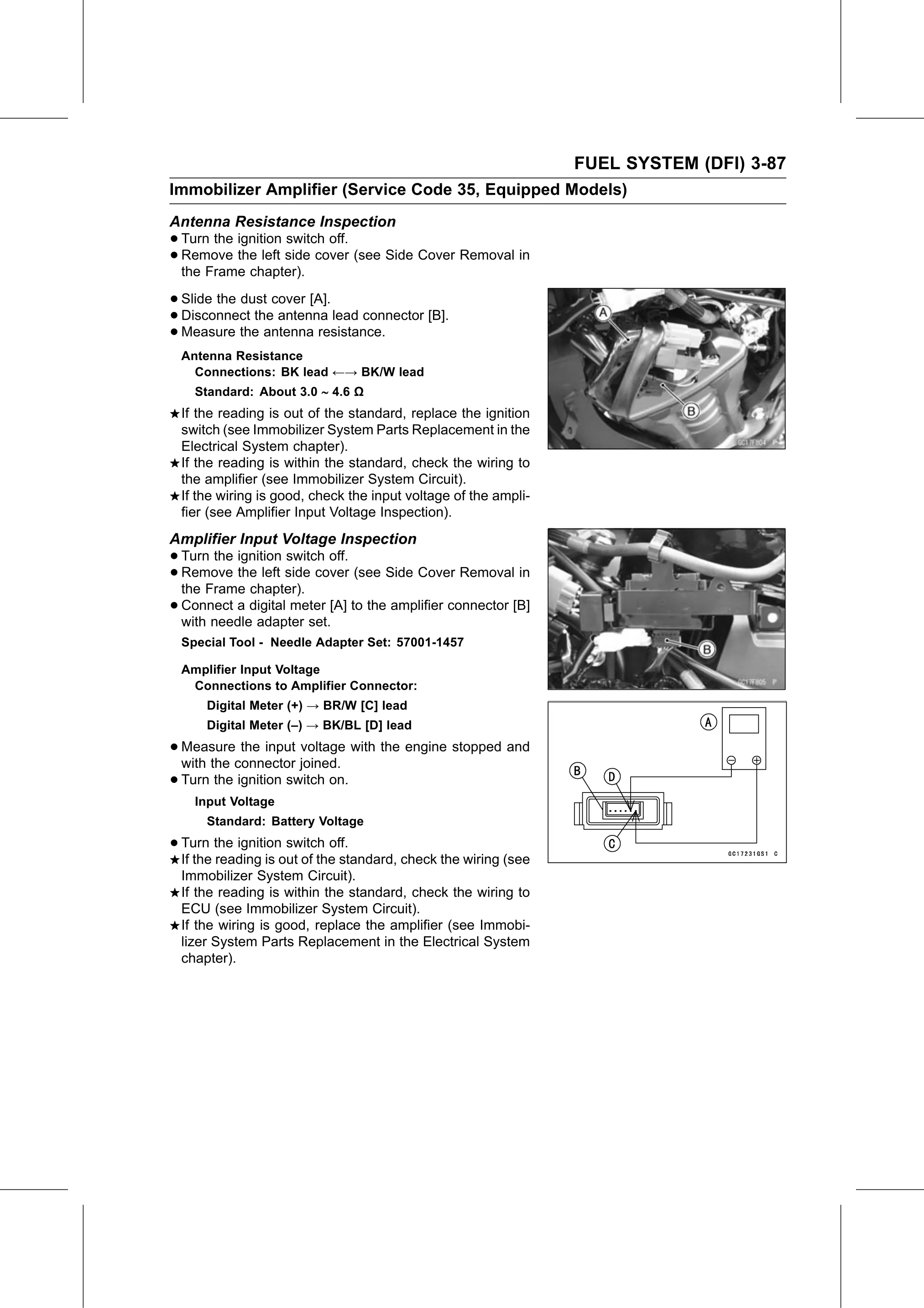
• Slide the dust cover [A].
• Disconnect  the antenna lead connector [B].
• Measure   the antenna resistance.
  Antenna Resistance
    Connections: BK lead ←→ BK/W lead
    Standard: About 3.0 ∼ 4.6 Ω
  If the reading is out of the standard, replace the ignition
  switch (see Immobilizer System Parts Replacement in the
  Electrical System chapter).
  If the reading is within the standard, check the wiring to
  the amplifier (see Immobilizer System Circuit).
  If the wiring is good, check the input voltage of the ampli-
  fier (see Amplifier Input Voltage Inspection).
Amplifier Input Voltage Inspection
• Turn the ignition switch off.
• the Framethechapter).
  Remove        left side cover (see Side Cover Removal in

• Connect  a digital meter [A] to the amplifier connector [B]
  with needle adapter set.
  Special Tool - Needle Adapter Set: 57001-1457

  Amplifier Input Voltage
   Connections to Amplifier Connector:
      Digital Meter (+) → BR/W [C] lead
      Digital Meter (–) → BK/BL [D] lead

• Measure   the input voltage with the engine stopped and
  with the connector joined.
• Turn the ignition switch on.
    Input Voltage
      Standard: Battery Voltage

• Turn   the ignition switch off.
  If the reading is out of the standard, check the wiring (see
  Immobilizer System Circuit).
  If the reading is within the standard, check the wiring to
  ECU (see Immobilizer System Circuit).
  If the wiring is good, replace the amplifier (see Immobi-
  lizer System Parts Replacement in the Electrical System
  chapter).