Service Manual — page 198 of 715
Fuel System (DFI) › ECU Power Supply Inspection
Text on this page
3-108 FUEL SYSTEM (DFI)
ECU

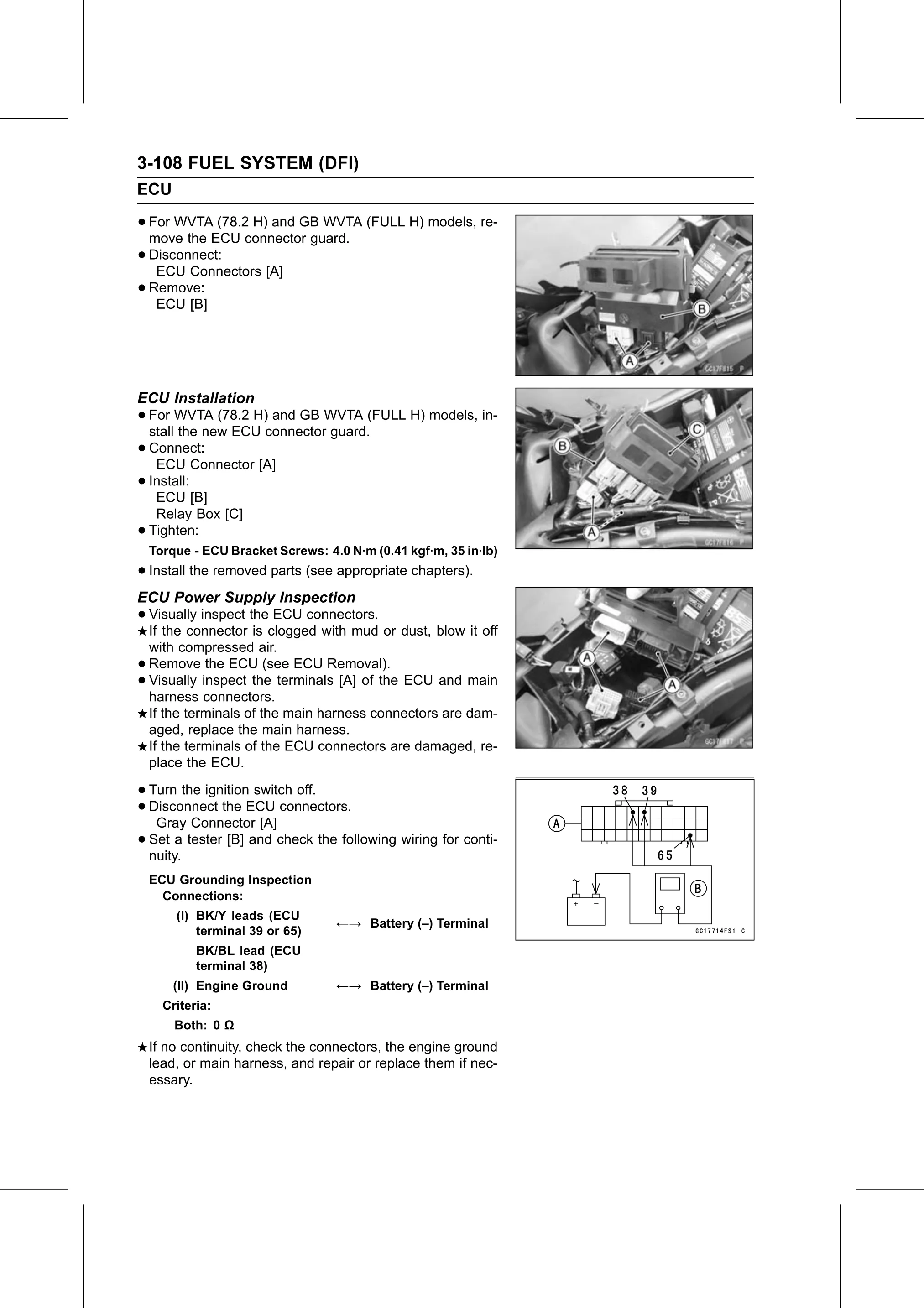
• For WVTA (78.2 H) and GB WVTA (FULL H) models, re-
  move the ECU connector guard.
• Disconnect:
   ECU Connectors [A]
• ECU [B]
  Remove:

ECU Installation
• For  WVTA (78.2 H) and GB WVTA (FULL H) models, in-
  stall the new ECU connector guard.
• Connect:
   ECU Connector [A]
• ECU [B]
  Install:

     Relay Box [C]
•   Tighten:
    Torque - ECU Bracket Screws: 4.0 N·m (0.41 kgf·m, 35 in·lb)
• Install the removed parts (see appropriate chapters).
ECU Power Supply Inspection
• Visually inspect the ECU connectors.
  If the connector is clogged with mud or dust, blow it off
    with compressed air.
•   Remove the ECU (see ECU Removal).
•   Visually inspect the terminals [A] of the ECU and main
    harness connectors.
    If the terminals of the main harness connectors are dam-
    aged, replace the main harness.
    If the terminals of the ECU connectors are damaged, re-
    place the ECU.

• Turn   the ignition switch off.
• Gray Connector
  Disconnect     the ECU connectors.
                       [A]
• nuity.
  Set  a  tester  [B] and  check the following wiring for conti-

    ECU Grounding Inspection
      Connections:
        (I) BK/Y leads (ECU
                                   ←→ Battery (–) Terminal
            terminal 39 or 65)
            BK/BL lead (ECU
            terminal 38)
        (II) Engine Ground         ←→ Battery (–) Terminal
      Criteria:
        Both: 0 Ω
    If no continuity, check the connectors, the engine ground
    lead, or main harness, and repair or replace them if nec-
    essary.