Service Manual — page 199 of 715
Fuel System (DFI) › ECU Power Supply Inspection
Text on this page
FUEL SYSTEM (DFI) 3-109
ECU
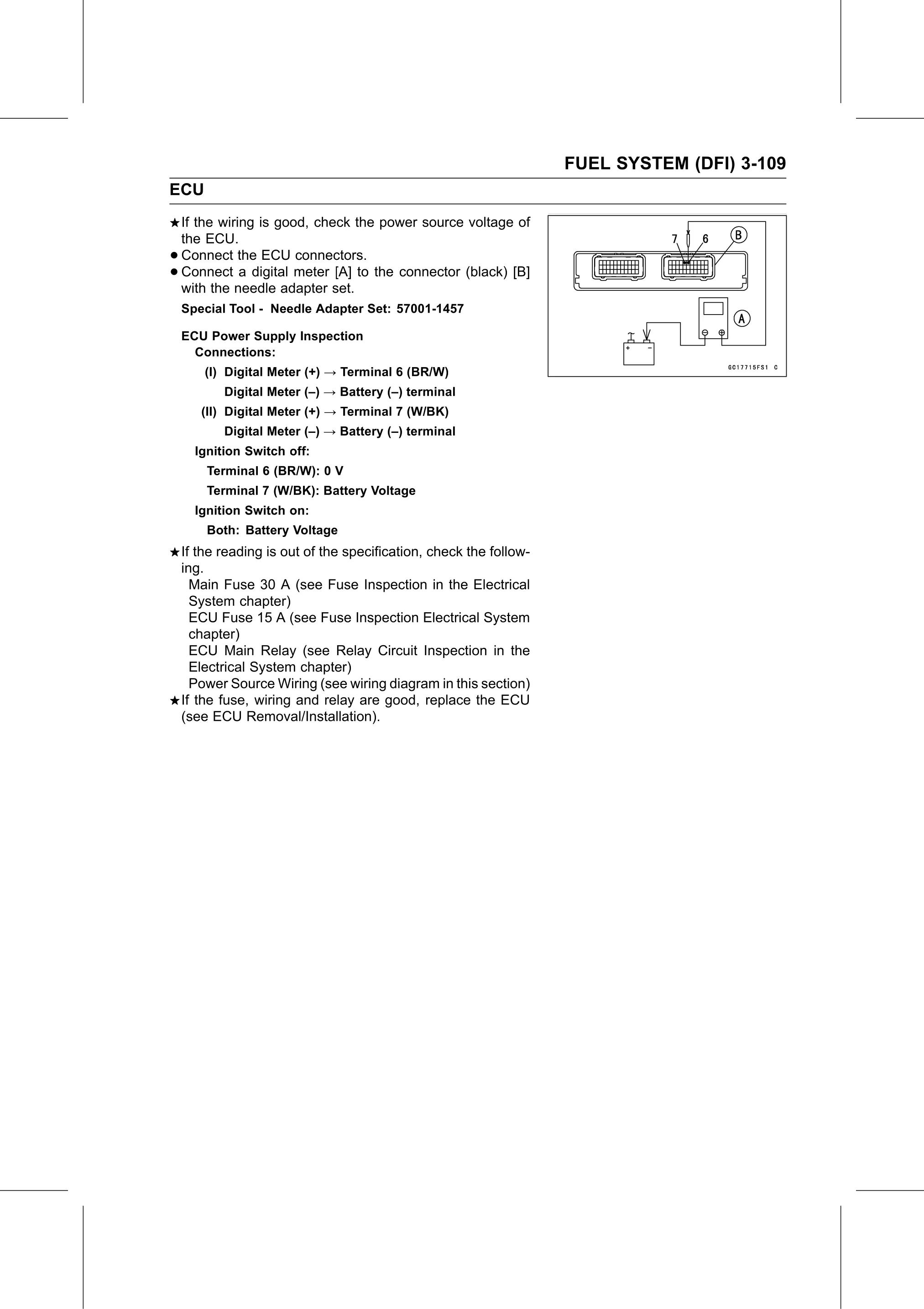
    If the wiring is good, check the power source voltage of
    the ECU.
•   Connect the ECU connectors.
•   Connect a digital meter [A] to the connector (black) [B]
    with the needle adapter set.
    Special Tool - Needle Adapter Set: 57001-1457

    ECU Power Supply Inspection
      Connections:
        (I) Digital Meter (+) → Terminal 6 (BR/W)
           Digital Meter (–) → Battery (–) terminal
       (II) Digital Meter (+) → Terminal 7 (W/BK)
           Digital Meter (–) → Battery (–) terminal
      Ignition Switch off:
        Terminal 6 (BR/W): 0 V
        Terminal 7 (W/BK): Battery Voltage
      Ignition Switch on:
        Both: Battery Voltage
    If the reading is out of the specification, check the follow-
    ing.
      Main Fuse 30 A (see Fuse Inspection in the Electrical
      System chapter)
      ECU Fuse 15 A (see Fuse Inspection Electrical System
      chapter)
      ECU Main Relay (see Relay Circuit Inspection in the
      Electrical System chapter)
      Power Source Wiring (see wiring diagram in this section)
    If the fuse, wiring and relay are good, replace the ECU
    (see ECU Removal/Installation).