Service Manual — page 274 of 715
Engine Top End › Camshaft Runout Inspection
Text on this page
5-24 ENGINE TOP END
Camshaft, Camshaft Chain
Camshaft, Camshaft Cap Wear Inspection
• Remove:
   Camshaft Caps (see Camshaft Removal)
• Placetheastrips
  Cut             of plastigage (press gauge) to journal width.
            strip on each journal parallel to the camshaft in-
    stalled in the correct position.
•   Tighten the camshaft cap bolts and upper camshaft chain
    guide bolts to the specified torque (see Camshaft Instal-
    lation).
                              NOTE
    ○Do not turn the camshaft when the plastigage is be-
      tween the journal and camshaft cap.

• Remove  the camshaft cap again, measure each clear-
  ance between the camshaft journal and the camshaft cap
    using plastigage [A].
    Camshaft Journal, Camshaft Cap Clearance
      Standard:      0.038 ∼ 0.081 mm (0.0015 ∼ 0.0032 in.)
      Service Limit:   0.17 mm (0.0067 in.)

    If any clearance exceeds the service limit, measure the
    diameter of each camshaft journal with a micrometer.
    Camshaft Journal Diameter
      Standard:     23.940 ∼ 23.962 mm (0.9425 ∼ 0.9434 in.)
      Service Limit:   23.91 mm (0.9413 in.)
    If the camshaft journal diameter is less than the service
    limit, replace the camshaft with a new one and measure
    the clearance again.
    If the clearance still remains out of the service limit, re-
    place the cylinder head unit.
Camshaft Runout Inspection
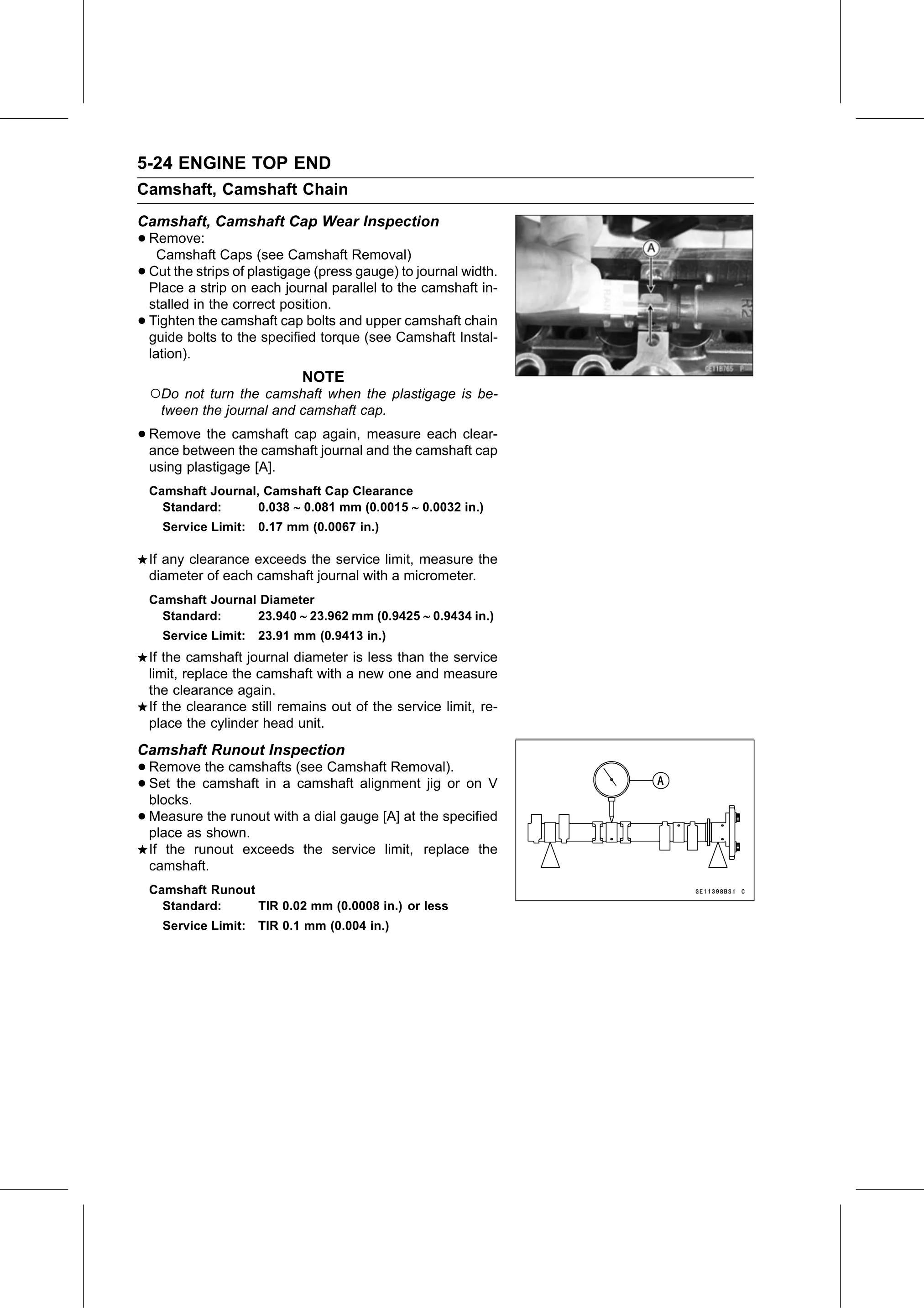
• Remove   the camshafts (see Camshaft Removal).
• blocks.
  Set the camshaft   in a camshaft alignment jig or on V

• Measure   the runout with a dial gauge [A] at the specified
  place as shown.
    If the runout exceeds the service limit, replace the
    camshaft.
    Camshaft Runout
      Standard:     TIR 0.02 mm (0.0008 in.) or less
      Service Limit:   TIR 0.1 mm (0.004 in.)