Service Manual (KLZ1000C) — page 79 of 762
Periodic Maintenance › Lights and Switches Operation Inspection
Text on this page
PERIODIC MAINTENANCE 2-57
Periodic Maintenance Procedures

• Turn  the ignition switch off.
•○For models
  The  all lights should go off.
                equipped with an immobilizer system, red im-
    mobilizer warning indicator light (LED) will blinks. Refer to
    the Immobilizer System (Equipped Models) section (see
    Immobilizer System (Equipped Models) section (16-89)).
    If the light does not go off, replace the ignition switch.
Second Step
•Turn the ignition switch on.
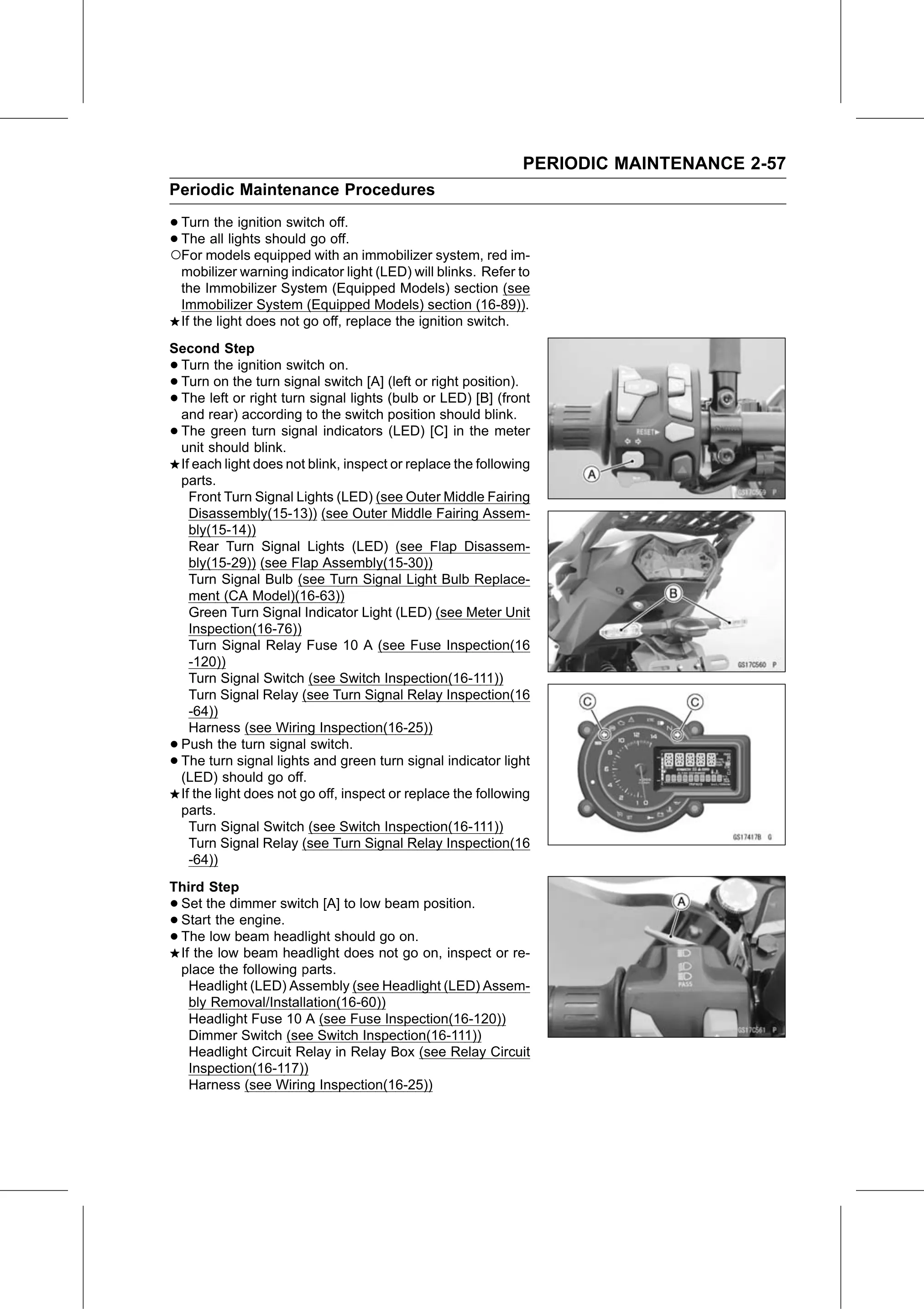
•Turn on the turn signal switch [A] (left or right position).
•The left or right turn signal lights (bulb or LED) [B] (front
 and rear) according to the switch position should blink.
•The green turn signal indicators (LED) [C] in the meter
 unit should blink.
 If each light does not blink, inspect or replace the following
 parts.
   Front Turn Signal Lights (LED) (see Outer Middle Fairing
   Disassembly(15-13)) (see Outer Middle Fairing Assem-
   bly(15-14))
   Rear Turn Signal Lights (LED) (see Flap Disassem-
   bly(15-29)) (see Flap Assembly(15-30))
   Turn Signal Bulb (see Turn Signal Light Bulb Replace-
   ment (CA Model)(16-63))
   Green Turn Signal Indicator Light (LED) (see Meter Unit
   Inspection(16-76))
   Turn Signal Relay Fuse 10 A (see Fuse Inspection(16
   -120))
   Turn Signal Switch (see Switch Inspection(16-111))
   Turn Signal Relay (see Turn Signal Relay Inspection(16
   -64))
   Harness (see Wiring Inspection(16-25))
•Push the turn signal switch.
•The turn signal lights and green turn signal indicator light
 (LED) should go off.
 If the light does not go off, inspect or replace the following
 parts.
   Turn Signal Switch (see Switch Inspection(16-111))
   Turn Signal Relay (see Turn Signal Relay Inspection(16
   -64))
Third Step
•Set the dimmer switch [A] to low beam position.
•Start the engine.
•The low beam headlight should go on.
 If the low beam headlight does not go on, inspect or re-
 place the following parts.
   Headlight (LED) Assembly (see Headlight (LED) Assem-
   bly Removal/Installation(16-60))
   Headlight Fuse 10 A (see Fuse Inspection(16-120))
   Dimmer Switch (see Switch Inspection(16-111))
   Headlight Circuit Relay in Relay Box (see Relay Circuit
   Inspection(16-117))
   Harness (see Wiring Inspection(16-25))