Service Manual (KLZ1000C) — page 596 of 762
Electrical System › Accessory Relay Inspection
Text on this page
16-114 ELECTRICAL SYSTEM
Switches and Sensors
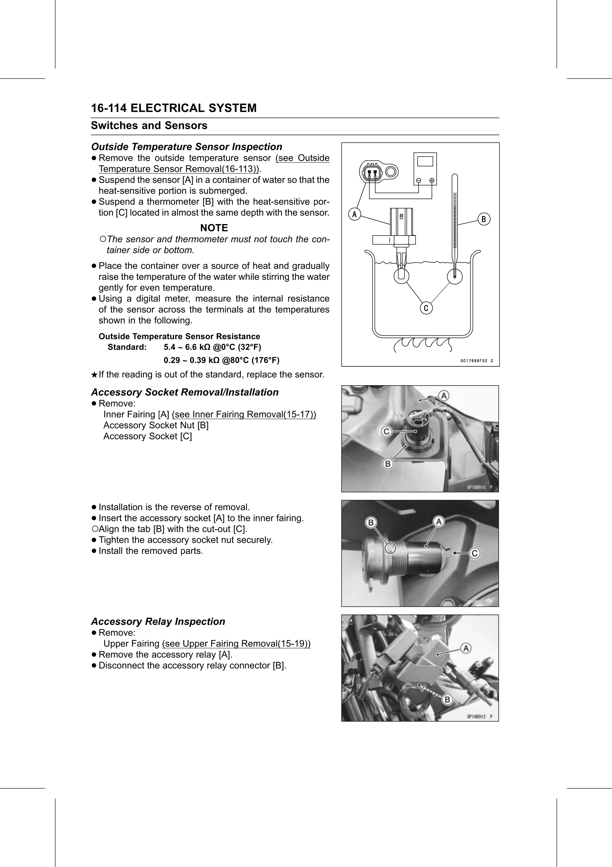
Outside Temperature Sensor Inspection
• Remove the outside temperature sensor (see Outside
Temperature Sensor Removal(16-113)).
• Suspend the sensor [A] in a container of water so that the
heat-sensitive portion is submerged.
• Suspend a thermometer [B] with the heat-sensitive por-
tion [C] located in almost the same depth with the sensor.
NOTE
○The sensor and thermometer must not touch the con-
tainer side or bottom.
• Place the container over a source of heat and gradually
raise the temperature of the water while stirring the water
gently for even temperature.
• Using a digital meter, measure the internal resistance
of the sensor across the terminals at the temperatures
shown in the following.
Outside Temperature Sensor Resistance
Standard: 5.4 6.6 kΩ @0°C (32°F)
0.29 0.39 kΩ @80°C (176°F)
If the reading is out of the standard, replace the sensor.
Accessory Socket Removal/Installation
• Remove:
Inner Fairing [A] (see Inner Fairing Removal(15-17))
Accessory Socket Nut [B]
Accessory Socket [C]
• Installation is the reverse of removal.
•○Insert the accessory socket [A] to the inner fairing.
Align the tab [B] with the cut-out [C].
• Tighten the accessory socket nut securely.
• Install the removed parts.
Accessory Relay Inspection
• Remove:
Upper Fairing (see Upper Fairing Removal(15-19))
• Disconnectthetheaccessory
Remove relay [A].
• accessory relay connector [B].