Service Manual (KLZ1000C) — page 658 of 762
Self-Diagnosis System › Oxygen Sensor Inspection
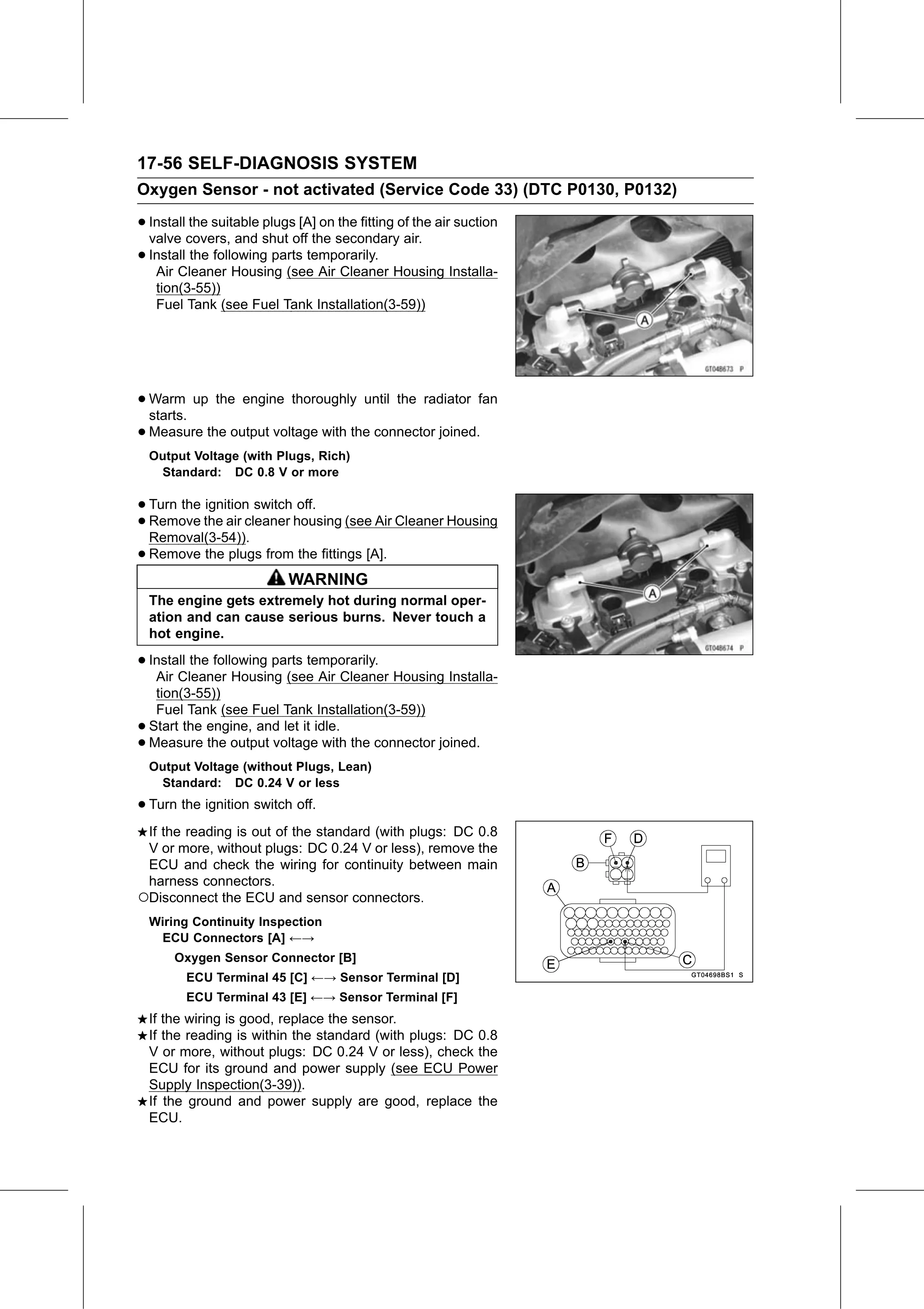
Text on this page
17-56 SELF-DIAGNOSIS SYSTEM
Oxygen Sensor - not activated (Service Code 33) (DTC P0130, P0132)

• Install the suitable plugs [A] on the fitting of the air suction
  valve covers, and shut off the secondary air.
• Install the following parts temporarily.
   Air Cleaner Housing (see Air Cleaner Housing Installa-
     tion(3-55))
     Fuel Tank (see Fuel Tank Installation(3-59))

• Warm
  starts.
          up the engine thoroughly until the radiator fan

• Measure the output voltage with the connector joined.
    Output Voltage (with Plugs, Rich)
     Standard: DC 0.8 V or more

• Turn the ignition switch off.
• Removal(3-54)).
  Remove   the air cleaner housing (see Air Cleaner Housing

• Remove the plugs from the fittings [A].
                           WARNING
    The engine gets extremely hot during normal oper-
    ation and can cause serious burns. Never touch a
    hot engine.

• Install the following parts temporarily.
   Air Cleaner Housing (see Air Cleaner Housing Installa-
     tion(3-55))
     Fuel Tank (see Fuel Tank Installation(3-59))
•   Start the engine, and let it idle.
•   Measure the output voltage with the connector joined.
    Output Voltage (without Plugs, Lean)
     Standard: DC 0.24 V or less

• Turn the ignition switch off.
 If the reading is out of the standard (with plugs: DC 0.8
 V or more, without plugs: DC 0.24 V or less), remove the
 ECU and check the wiring for continuity between main
 harness connectors.
○Disconnect the ECU and sensor connectors.
    Wiring Continuity Inspection
     ECU Connectors [A] ←→
        Oxygen Sensor Connector [B]
          ECU Terminal 45 [C] ←→ Sensor Terminal [D]
          ECU Terminal 43 [E] ←→ Sensor Terminal [F]
    If the wiring is good, replace the sensor.
    If the reading is within the standard (with plugs: DC 0.8
    V or more, without plugs: DC 0.24 V or less), check the
    ECU for its ground and power supply (see ECU Power
    Supply Inspection(3-39)).
    If the ground and power supply are good, replace the
    ECU.