Service Manual — page 546 of 715
Frame › Upper Fairing Bracket Installation
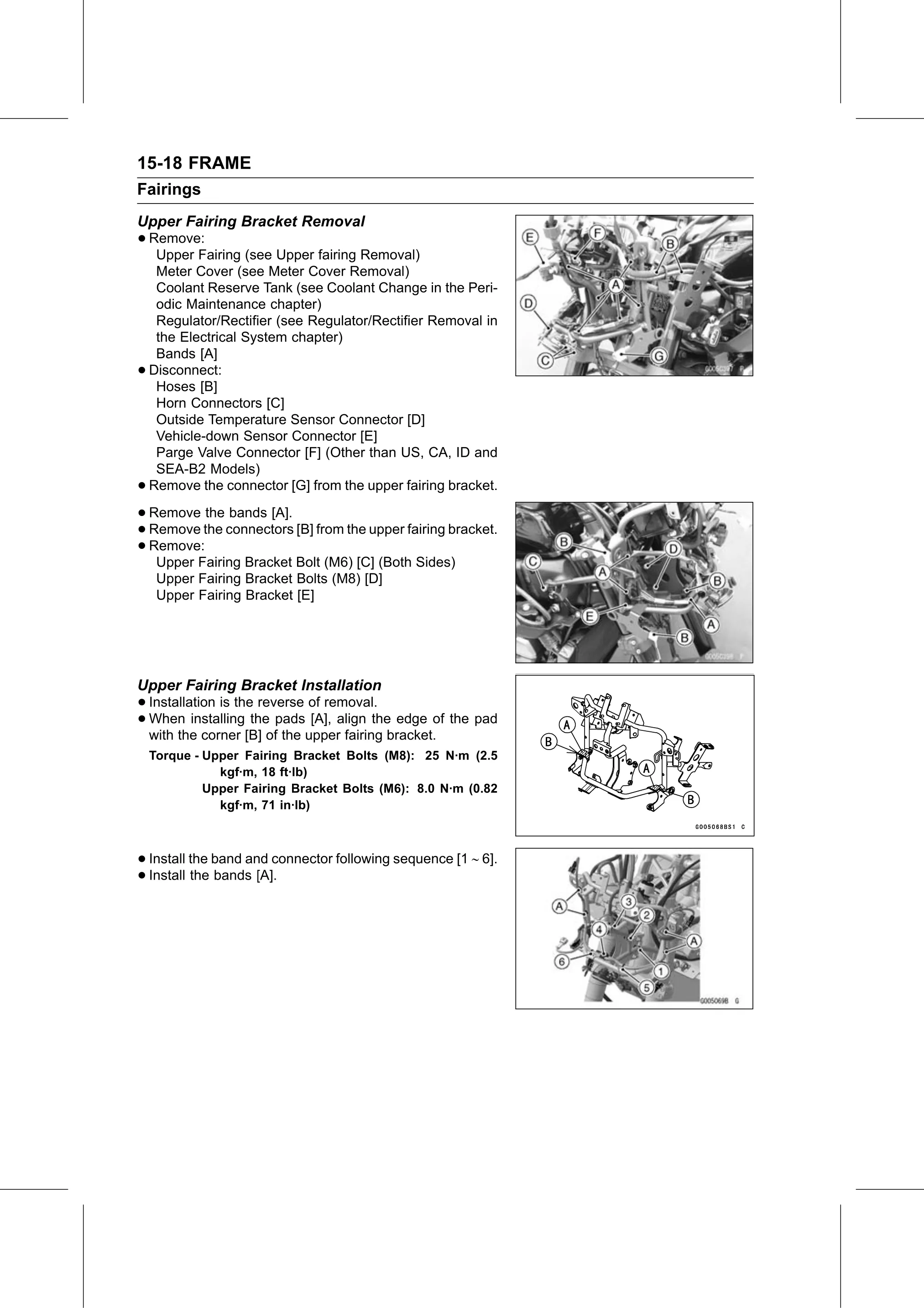
Text on this page
15-18 FRAME
Fairings
Upper Fairing Bracket Removal
• Remove:
   Upper Fairing (see Upper fairing Removal)
     Meter Cover (see Meter Cover Removal)
     Coolant Reserve Tank (see Coolant Change in the Peri-
     odic Maintenance chapter)
     Regulator/Rectifier (see Regulator/Rectifier Removal in
     the Electrical System chapter)
     Bands [A]
•   Disconnect:
     Hoses [B]
     Horn Connectors [C]
     Outside Temperature Sensor Connector [D]
     Vehicle-down Sensor Connector [E]
     Parge Valve Connector [F] (Other than US, CA, ID and
     SEA-B2 Models)
•   Remove the connector [G] from the upper fairing bracket.

• Remove the bands [A].
• Remove: connectors [B] from the upper fairing bracket.
  Remove the
• Upper Fairing Bracket Bolt (M6) [C] (Both Sides)
     Upper Fairing Bracket Bolts (M8) [D]
     Upper Fairing Bracket [E]

Upper Fairing Bracket Installation
• Installation is the reverse of removal.
• with the corner [B]theofpads
  When    installing            [A], align the edge of the pad
                           the upper fairing bracket.
    Torque - Upper Fairing Bracket Bolts (M8): 25 N·m (2.5
               kgf·m, 18 ft·lb)
             Upper Fairing Bracket Bolts (M6): 8.0 N·m (0.82
               kgf·m, 71 in·lb)

• Install the band and connector following sequence [1 ∼ 6].
• Install the bands [A].